A related question is a question created from another question. When the related question is created, it will be automatically linked to the original question.
If you have a related question, please click the "Ask a related question" button in the top right corner. The newly created question will be automatically linked to this question.
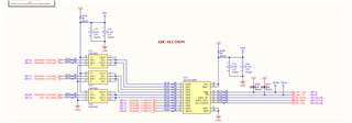
Depending on the speed of your I/O clock to the TLV2553, you may need to include an R/C ahead of the inputs you show using the LM358 shown in your schematic. Adding a driver to the input channels 6-10 may also be required. Beyond that, make sure you have a good ground connection to REF- and GND. Also make sure you have the bypass and 10uF bulk capacitor close to pins 20 and 14 respective.
Thank you so much for the feedback. We are not planning to use high spped for the SPI CLK (IO Clock), and we have buffers for pins 6-10 also, any other concerns you think with the design?
Just to keep the input traces as short as possible, and keep the reference clean. Feel free to send over the layout when you are ready to move to copper and we'll review that for you as well.