This thread has been locked.

If you have a related question, please click the "Ask a related question" button in the top right corner. The newly created question will be automatically linked to this question.

ADS131M08: Sampling rate is half than expected

Part Number: ADS131M08

The sampling rate i am getting is only half than expected.

According to page 23 of the datasheet at power mode HR with a clockin frequency of 8.192MHZ and a OSR setting of 1024 i should be getting 4 000 sample per second. Instead i am getting only 2000 Samples per second. 

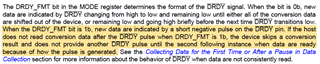
I have not changed any other register settings exempt for the Mode Register setting it to 0x0111 (clearing the RESET bit and setting the DRDY_FMT to pulse mode)

writeSingleRegister(MODE_ADDRESS, 0x0111)

Increasing or decreasing the OSR also yields only half the expected sampling rate. For example

512  -    4ksp/s only  instead of 8ksp/s

256  -    8ksp/s only  instead of 16ksp/s

128  -  16 ksp/s only instead of 32ksp/s

I think i have narrowed down the culprit. Powering off the device, and turning it back on with ONLY the 8.192Mhz signal (no SPI comunnication was done with the device). I am able to get the 4ksp/s. 

But upon executing  writeSingleRegister(MODE_ADDRESS, 0x0111).  I am getting half of the expected sampling rate

suspecting that my writeSingleRegister function broke some other register settings , i went ahead and read all global-setting registers ( registers 0x02 to 0x08) to check if  I indeed corrupted something. Here are the results

REG ADDRESS REG NAME RESET VALUE MY VALUE
0x02 MODE 0x0510 0x0111
0x03 CLOCK 0xFFE0 0xFFE0
0x04 GAIN1 0x0000 0x0000
0x05 GAIN2 0x0000 0x0000
0x06 CFG 0x0600 0x0600
0x07 THRSHLD_MSB 0x0000 0x0000
0x08 THRSHLD_LSB 0x0000 0x0000

I have even tried not touching the MODE_RESET bit by using writeSingleRegister(MODE_ADDRESS, MODE_DEFAULT | 0x0001). It would seem that changing DRDY_FMT causes the problem. 

What do i do to get it back to the proper sampling rate while still having a pulse drdy format??

  • Hi Peter,

    Thank you for your post. It appears your images did not attach correctly, can you try uploading them again?

    The reason for this is likely because you are not actively reading data while the conversions are running. The DRDYn behavior will change in both format setting whenever new conversions are not read at regular intervals. When DRDY_FMT = 0b, a missed conversion results in a very short low-to-high transition just before the next DRDYn falling edge. When DRDY_FMT = 1b, the device skips a conversion result if the previous conversion was not read. A DRDYn pulse will only be generated after the next conversion is completed in that case, essentially reducing the interrupt frequency to one-half the data rate:

    In short, you'll need to read out the entire frame after each DRDYn interrupt to maintain a regular data rate period.

    Regards,

    Ryan

  • That indeed solved the problem ! Thank you. 

    While im here id like to know if indeed i am reading an entire frame, from what i understand and as you have mentioned it is important that the entire frame is read. How many bytes is an entire frame?

    response  >  channel0  >  channel1  >  channel2  >  channel3  >  channel4  >  channel5  >  channel6  >  channel7 >  CRC

    So if i set the word length to 2 an entire frame is 20 bytes long, word length of 3 = 30 bytes long, word length of  4 = 40 bytes long


    Is CRC always there even if crc is disabled?

  • Hi Peter,

    Yes, the output CRC is always there. Only the input CRC can be disabled.

    An entire frame will always include 10 words as you've outlined above (with the exception of possibly RREG/WREG commands). The word length can be adjusted from two to four bytes. The output CRC is always output at the end of the frame, but the data sheet is not entirely clear when it says "the host can ignore" it. I believe you can end the frame after reading Channel 7 data by bringing CSn high. Otherwise, you could just read the entire frame and ignore the CRC word.

    Best regards,

    Ryan