This thread has been locked.

If you have a related question, please click the "Ask a related question" button in the top right corner. The newly created question will be automatically linked to this question.

TLC7524 Bipolar Operation: Can't seem to get it working!

Other Parts Discussed in Thread: TLC2274, TLC7524

I'm building a device to generate a sine wave. I have been working from the data sheet, and thus far haven't had any problems using the chip as a unipolar device. However, I can't seem to ge the bipolar mode to work. I have checked over and over and over, and I have connected the device as per page 7 of the data sheet:


http://datasheet.octopart.com/TLC7524CN-Texas-Instruments-datasheet-153174.pdf


Is there something I'm not doing correctly? Currently I have Vref at 5V, VDD at 5V, and am feeding 0x80 (1000000 in binary) into the data ports, and am not using RA or RB for gain control - I should be getting zero, or something very close to that. Instead, It appears the device is still unipolar.

I am operating using a single power supply, do I need a dual power supply to power the op amplifiers? I am measuring the voltage between 'Output' and OUT1.

  • Hello Liam,

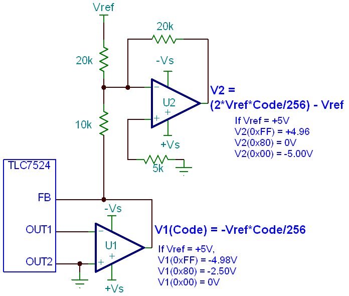
    You really need to use dual power supplies for both amplifiers because they need to invert and offset a negative voltage. Also, voltages should be measured with respect to ground not OUT1.

    ±10V dual power supply should be enough to make everything work fine. Just make sure that your amplifiers can handle the supply.

    In the figure at the bottom of this post, there are three code examples that you can use to verify the outputs of the amplifiers. I hope it helps.

    By the way, could you tell us what amplifiers you are using? We just want to check the common mode input range. This parameter is very important to avoid saturating the amplifiers.

    Let us know what happens. We will try to help you as much as possible to get your circuit working.

    Best regards,

  • Thanks Rafael, that's a lot of help! I'm using TLC2274 quad package amplifier. I see that it support supports up to ±16V, is that correct? Could I get away with using ±5V instead of ±10V for the amplifiers, and if so, what would be the ramifications?

  • Hi Liam,

    Thanks for the info.The common mode input range allows a 0V at the inputs of the TLC2274 with ±5V. However, due to the output range limits of -Vs+1.5V and +Vs-0.75, you need to use at least a ±6.5V dual supply to get the full range of the TLC7524 with Vref = 5V.

    Another option is to change Vref to 3.3V. With this reference value, a ±5V supply should work fine with the TLC2274.

    If you see any issues, let us know.

    Best Regards,

  • Ahh, excellent, thank you for all your help. I'll make the necessary modifications, and le you know what happens.

  • Hi Liam,

    I just noticed that you modified your previous post. About the supplies for the TLC2274, they should not exceed ±8V. I believe that the ±16V you mentioned before refers to the differential input range, and it doesn't apply to supply range.

    Thus, be very careful with the supplies.

  • Well spotted, yes it appears I had read the wrong number, thanks for pointing that out.

  • Okay, so, it's been a while, but I've got DAC working - sort of!


    I've been using a microcontroller to swing the inputs from 0x00 -> 0xFF, And it seems to function as expected, however, I'm only getting a voltage range of 1.94 to -3.64. Now, my circuit has Ra and Rb for gain adjustment, however the fact that the output isn't centred around 0V is of concern. The OP amp is powered by +-5V, and the difference measured across it is 10.04V. Below is an image showing the circuit I have wired:

    A1 corresponds to amplifier 1, A2 corresponds to amplifier 2.

    Any help is much appreciated.

  • Aha, fixed it myself. The problem is the R05 and P01 in the diagram above, you need to have the same voltage going into REF and R03 (currently VCC) for it to function correctly. Silly mistake, I'm sure. I've removed RO5, and have replaced VCC on R03 with the voltage going into the REF pin. Works great!