Other Parts Discussed in Thread: ADS114S08
Good morning,
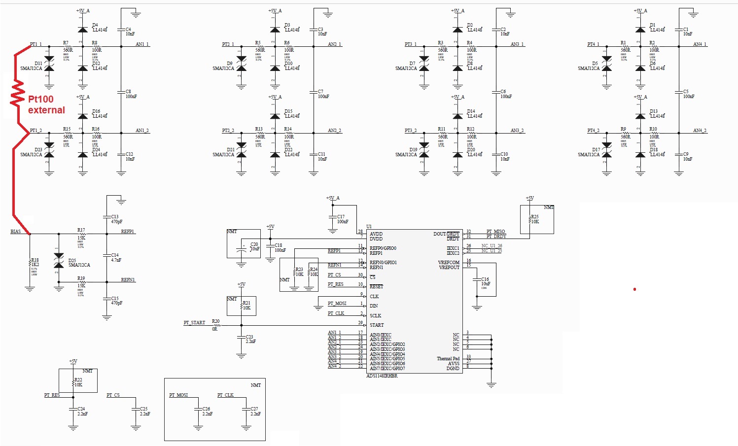
we are using the ADS1148IRHBR to measure the temperature of four PT 100 sensors.
In the attached file, you can find the schematic.
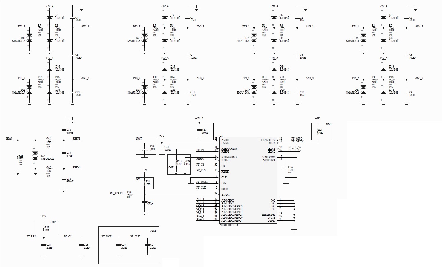
Our logic is the following:
-) we consider valid values of resistance if the measured resistor is 76,65ohm < value < 212ohm
-) if the resistor is >212ohm, we indicate "circuit open" on the respective input channel
-) if the resistor is <76,65 ohm, we indicate "short circuit" on the respective input channel
We are in the prototyping phase and we realized 7 samples of the hardware.
5 samples work fine, but we have problems on 2 samples.
On these 2 samples the behaviour is the following:
-) if we connect a resistor between PTx_1 and PTx_2 (where x is a generic channel) with a value between 76,65ohm and 212ohm the measure is correct
-) if we leave the circuit OPEN from PTx_1 and PTx_2 (channel open), the measure is very instable and the measure floats irregularly between values from 76,65ohm and 212ohm and values < 76.65 ohm.
This is incorrect because the detected values must be >212ohm (stable value) which indicate circuit open.
NOTE 1: the incorrect behaviour regards all the 4 channels.
NOTE 2: the other 5 samples works fine.
We tried to:
- remove all the clamping diodes LL4148
- remove all the TVS SMAJ12CA
- remove the filter capacitors
- substistute the filter capacitors
but all of these operations don't obtain any positive results.
Do you note some problems in the schematic?
From the described behaviour, can you understand the cause?
Please can you help to understand the cause? 5 samples at the end work fine
We soldered the board with a plate between 220°C and 240°C? Is it possible that the component was damaged during the soldering process? If yes, please can you indicate the instructions for the soldering with a plate.
Please let me know as soon as possible.
Best regards.
Diego Bolzoni