Other Parts Discussed in Thread: ADS127L01, REF6025, OPA320
I have a strain gauge Wheatstone bridge setup with a 2.8V LDO (TPS7A2028) supplying power to the entire circuit from a 3.3V battery. I purchased a ADS127L01EVM evaluation module to test out performance of ADS127L01. At this stage I wouldn't bother setting up a proper voltage reference IC yet. We haven't decided for sure what our reference voltage would be but it'll be somewhere between 1.2V to 1.4V and we'll be testing different reference voltages with just a simple voltage divider.
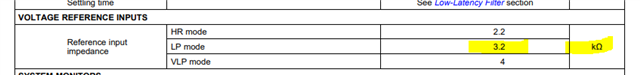
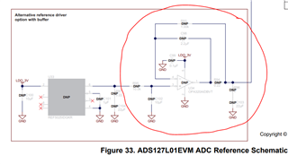
I then proceeded to remove the internal reference voltage of 2.5V on the ADS127L01EVM by removing the zero-jumper resistor R90, and connected my external reference voltage to the TP19 probe with a test lead hook. My external reference voltage is a voltage divider between two 100kOhm resistors dividing the 2.8V from the LDO into two 1.4V. When I connected the 1.4V reference voltage to the TP19 (or REFP) I got near 0V at TP19. All voltage drops appeared across the first 100-kOhm resistor, implying the REFP shorting the second 100-kOhm resistor with an input impedance much lower than 100-kOhm. I measured the current (drawing some ~4mA) and found out the REFP has only a 2.3k-Ohm input impedance!!
I changed 100-kOhm voltage divider resistors to 350-Ohm and finally got myself a 1.3V voltage reference (still 0.1V off from the ideal 1.4V due to low parallel input impedance of REFP, but it's fine - we wanted a reference slightly lower than the center level anyway), but that troubled me as to why REFP has such low input impedance.
- Shouldn't voltage reference input has high impedance? Is the evaluation board damage or does it really have a low impedance input at REFP?
- If I can't source an exact voltage reference (e.g. 1.25V), I will have to probably voltage divide a the 2.5V in REF6025 into 1.25V. But if REFP has low input impedance, the voltage after dividing can hardly be accurate to 1.25V unless I use very low resistance, perhaps sub-10-Ohm resistors for the voltage divider (even a 100-Ohm could yield up to 5% error). Is there a better workaround?