Part Number: ADS131M08
Hello,
I am working with ADS131M08 part but without using TI SimpleLink Library. I am using ADS131M0x Example C Code as reference but updated the following function with ioctl() call:
spiSendReceiveArrays(const uint8_t dataTx[], uint8_t dataRx[], const uint8_t byteLength)
{
struct spi_ioc_transfer xfer;
xfer.tx_buf = reinterpret_cast<uint64_t>(dataTx);
xfer.rx_buf = reinterpret_cast<uint64_t>(dataRx);
xfer.speed_hz = m_speed; //8192000
xfer.bits_per_word = m_bitsPerWord; //24 bits/word
xfer.len = 4; //byteLength;
//SPI MODE is set to SPI_MODE_1
int32_t ret = ::ioctl( m_fd, SPI_IOC_MESSAGE(1), &xfer );
if (ret < 0)
{
printf("%s:%d: ERROR: Failed SPI tx: ret(%d)\n", __FUNCTION__, __LINE__, ret);
}
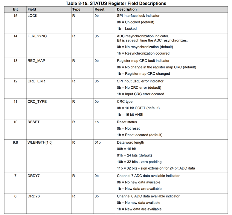
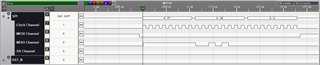
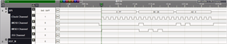
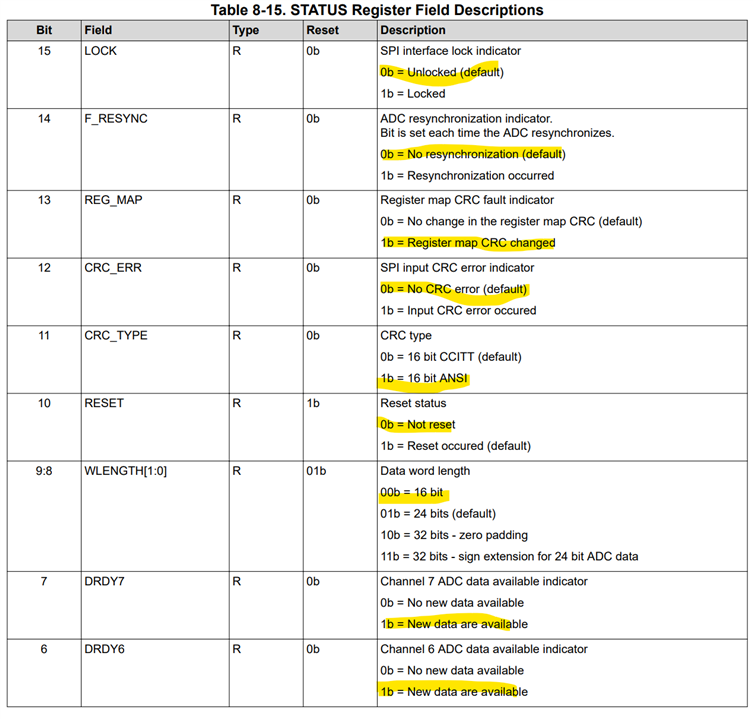
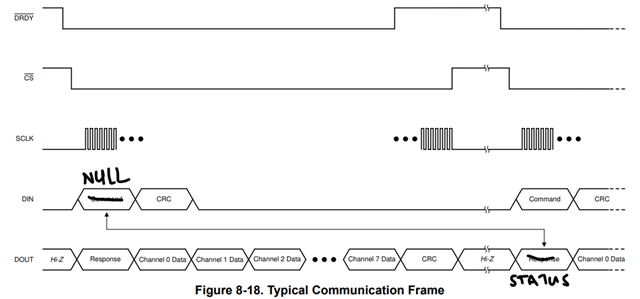
}When dataTx set to zeros, I am not getting STATUS reg value 0x500 (default) (ads131m08.pdf, page 42 Table 8-11 Command Def). Do you have examples where Reference C code example use ioctl calls?
Thank you and appreciate you help.
nkumar