


Other Parts Discussed in Thread: ADS1248
Hi,
We are doing a redesign were will be using the ADS1220 for temperature measurement using type K thermocouples. We use the 10uA burn-out current sources to detect broken sensors, the BCS should be disabled for 1ms after each readout, 19 cycles later this should clip the ADC. But we where not seeing this, upon inspection with our diff probe amp and scope it shows that the current source disables itself after 550us.
Some background:
We have 32 inputs, sets of 4 are muxed by an 74HC4052, these 3 are then muxed by another 74HC4052 and fed to a ADS1220 (we have 3 of them) on channel 1, channel 2 is used for cold junction measurement.
(the reason of the second mux is because the original design used an 8ch ADC).
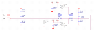
Our input circuit:
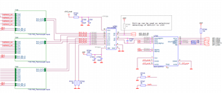
The ADC:
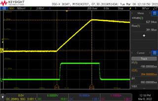
Upon inspecting the input signal when the TC is shorted we can see that the BCS is enabled for 550us and than shuts down. For debug purposes we fooled around with the time that the BCS is enabled, but we concluded that it will always disable after 550us, shorter is possible though. The green trace is the moment that the MCU enables the BCS (in this case it should have been 630us (as i stated above our target was 1ms but we changed this for debug purposes).
To make sure our FW on the MCU was not to blame I also had a look with a logic analyzer.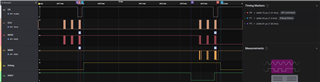
Now what bothers me is the DRDY line going low, roughly at the moment we see our BCS disable, could this be a coincidence? The ADC's are in single shot so I would not expect the data ready to change.
Any help is greatly appreciated.
Cheers,
Daan

