This thread has been locked.

If you have a related question, please click the "Ask a related question" button in the top right corner. The newly created question will be automatically linked to this question.

[FAQ] ADC128S102-SEP: Can I apply input signals before the analog supply (Va)

Part Number: ADC128S102-SEP
Other Parts Discussed in Thread: ADC128S102

Hello,

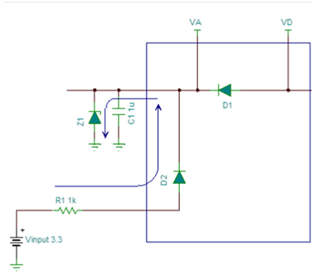
We have an application where the analog inputs are active before the power up of the analog supply (Va) is complete.  What are the implications of this condition and how can we improve reliability of the application?

  • The results of this condition will depend on the system architecture when the supplies are off.  Common power-supply architectures may be floating (high-z), partially driving to a voltage potential (mid-Z), or connected to GND (low-z / short) when they're "OFF". 

    Here are some things that can happen based on the condition of the VA supply:

    1. VA floating during power-down
      1. This would indicate the VA supply output is high-z (>100kΩ) when powered-down/disabled
      2. In this case the VA supply can get fully, or partially powered up from the inputs because VA will be a diode drop less than the input voltage.  It doesn’t take much current to power the ADC into the static condition, and so if the VA voltage gets above +2.7V the ADC will likely be partially on. 
      3. While this ADC doesn’t have any known power-supply brown-out issues (other than not allowing VD to be higher than VA by more than 300mV at any time even during brownouts), It’s still not great to have the ADC sitting in a partially biased state because when the real power supply is enabled some ADCs (again no known cases with ADC128S102) wont’ properly go through their POR sequence and may not start up properly.
    2. VA hard tied to GND
      1. This would indicate the LDO has an internal switch from VOUT to GND when powered down, or there is a separate circuit (usually a FET) that connects the VA supply to GND during power-down conditions.
      2. In this case the current needs to be limited into the input pins because after VIN is greater than roughly ~0.5V the internal ESD diode will conduct to GND and current will flow.  Max current into any one input is 10mA and not more than two can be at 10mA at a time, or any other combination that exceeds 20mA of total unwanted conduction.  If the condition is known to happen regularly then we recommend to limit the current to <1mA to stay away from the max ratings.
    3. VA partially biased during power-down
      1. This would indicate that the LDO output has an internal pull to a known potential, or there is a leakage path that allows it to rise.
      2. Similar effects as #1 in how the ADC could be affected based on how high the Va voltage gets, and similar to #2 if the biasing is strong enough to sink >10mA.

    In conditions where the VA supply is not limited a Zener / TVS diode placed on the supply can help prevent accidental over-voltages on VA depending on what's connected externally to the inputs in this condition.