- Ask a related questionWhat is a related question?A related question is a question created from another question. When the related question is created, it will be automatically linked to the original question.
Hi experts,
I've watched videos in 'TI precision labs - ADCs' and benefited from it. But I'm still confused about some parameters of practical ADCs and their usage for my design.
As for ADS1281, I've got:
'f_mod' (sample rate as I understand): 1 MHz
data rate: 1000 SPS, for example.
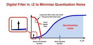
FIR Bandwidth: 0.413 x 1000 = 413 Hz
(I'm personally interested in this kind of DC-optimized delta-sigma ADCs because of their high SNR, although it might be excess my need.)
Due to my unfamiliarity with delta-sigma ADC's principle, I'm confused about if these parameters suit my design, which is my main problem.
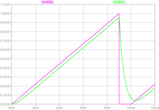
My input signal shows as follows:
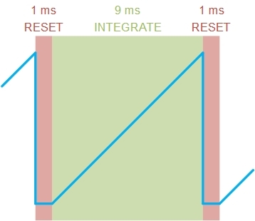
The sawtooth wave's period is 10 ms containing 9 ms "integrate" time and 1 ms for the "reset." I'm interested in the slope of the "integrate" phase.
These are my questions:
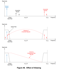
1. Is 1/2 of 'f_mod' the "input signal frequency range" without aliasing? Further, can the sampling accuracy (compared to the practical transient voltage) be guaranteed when input is less than 1/2 'f_mod'?
My input signal's upper limit frequency containing step components is about 30 kHz, which is much smaller than 0.5 MHz (1/2 f_mod), is which means each over-sampling point is accurate?
2. Because my signal has a step part, which parameters can I reference to ensure that the modulator can fastly follow the transient voltage reset? (Such as the 'slew rate' in OPAMP? But I can't find it in ADS1281's datasheet.)
Or it only depends on the input driver circuit's time constant? In this case, I think it's not a problem with proper design.
3. Will the low cut-off BW of the FIR filter lower my time-domain sampling accuracy?
I thought that the digital filter averages (decimates) 1024 over-sampling points (OSR) for one output data point. Hence in my plan A, I use a 1000 SPS data rate to sample my 100 Hz sawtooth wave, like the figure below, where I assume that the "selected data points" should be accurate.

(If I use a wide-band ADC and obtains much more data points as a plan B, eventually I still have to average them manually rather than utilize the integrated FIR filter)
But I'm worried about the feasibility of my design because I don't understand the 413 Hz FIR bandwidth's meaning. I tried to simulate it with an analog filter with the same BW, leading to an inaccurate output. So what does the FIR BW means? Will it influence my design accuracy?
Thank you!