This thread has been locked.

If you have a related question, please click the "Ask a related question" button in the top right corner. The newly created question will be automatically linked to this question.

ADS1291: ADS1291 SPS

Part Number: ADS1291

Hi

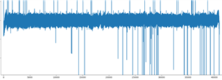
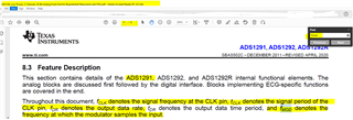
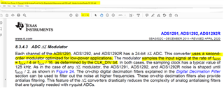
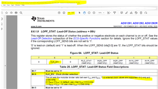
I'm measuring wrist ECG with ADS1291.

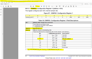
Currently, I set it to 500 sps and collect data.

I'm measuring it in 30 seconds, but I got 41,000 data.

I think it's sps = hz.

So I think we should get 15,000 data if we measure 500 sps and 30 seconds.

I wonder if I'm wrong.

Help me. Thank you..

  • Hi,

    Highly appreciate for using TI's products.

    This ticket has been received/viewed, and I will get back to you between 3~5 days.

    May I ask some more questions to collect more detail info?

    Do you use any evaluation kit/board?

    According to "ADS129x Low-Power, 2-Channel, 24-Bit Analog Front-End for Biopotential Measurements datasheet (Rev. C)", 

    What clock and CLK_DIV are you using/setting?


    Did you write the correct value to the CONFIG1 register?

    In the meantime, let me circle back with our engineer team.

    Appreciate.

  • Hi.

    Thank you for your reply.

    I checked the part you pointed out.

    My spi frequency is 250Kbps.

    so fCLK is 250Kbps(1Hz = 2bps , 250Kbps = 500kHz Is this right?)

    And I set the CLK_DIV bit to 0.

    so fMOD = fCLK/4 = 125kHz

    And I want 500hz, 125k / 250 = 500hz.

    Set DR0 to DR2 bits to 0,1,0

    I just did it like this. Is this right?

    Thank you.

  • Do you use any evaluation kit/board?

    I would suggest start from checking the Clock input first -

    Would you please check which Clock are you using? Internal or External? If possible, would you please use scope probe to check the clock frequency at CLK pin?

    CLK pin is an input(if using external clock) pin for you to connect/provide external clock(crystal oscillator or square wave from Host(uController/FPGA) to provide clock.

    SCLK is an input pin for SPI communication that should come from Host(uController/FPGA).

    Note that CLK is not the same as SCLK.

    Double check the following and set accordingly to meet the clock sources(external or internal) -

    Clock selection is controlled by the CLKSEL input pin and the CLK_EN register bit.
    The CLKSEL pin selects either the internal or external clock. The CLK_EN bit in the CONFIG2 register enables
    and disables the oscillator clock to be output in the CLK pin.

    Also, Could it be possible it's sampling in the correct rate you set, but the host is reading longer/larger block of data to show?

    You could test/verify this by injecting known number of cycles of low frequency, low amplitude sinusoid wave or using one of the FLUKE BIOMEDICAL Patient Monitor Simulators.

  • Hi.

    Thank you for your reply

    The circuit diagram shows it as below

    I think the part I painted is right

    But I'm not sure yet. Help me

    Thank you.

  • What are the voltages reading for AVDD, AVSS and DVDD?

    Could you double check both VDD and VSS are quiet and clean?

    Also, Can you check the proper power up sequence -

    From the schematic you provided, it's using the internal clock of 512 kHz.

    Can you try write 1 to Bit 3(CLK_EN) of CONFIG2 register and use Oscope to check whether the CLK pin is 512kHz clock?

    The sampling clock has a typical value of 128 kHz; so sampling rate is not the same as the data rate.

    if you write 010 to DR[2:0], the sample rate is still 128kHz and the data rate will be 128K/256 = 500 SPS.

    Please probe to check the SCLK signal is clean and quiet. What is your SCLK frequency?

    You may want to use oscope to probe the following during the data transmission(read/write from/to the device) -

    Depends on the DVDD supply voltage, the SCLK period needs to be longer than 50 or 66.6 ns -

    May I know your SCLK period or frequency? 

    In the schematic, the START pin is tied to LOW, so the START command needs to be sent to start the conversion.

    If possible, Can I see the scope screenshot of CLK, /CS, SCLK, /DRDY, DIN, DOUT when you are reading data?

  • I solved it. Thank you!