This thread has been locked.

If you have a related question, please click the "Ask a related question" button in the top right corner. The newly created question will be automatically linked to this question.

LM10011: Using DIP switch to control the VID Digital Inputs

Part Number: LM10011
Other Parts Discussed in Thread: TPS543C20

Dear TI Team,

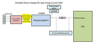
We are planning to use LM10011 Current DAC to vary the output voltage of Buck regulators on our board.

As VID control signals should be given externally, can we use DIP switch with Pull-up and Pull- down options to set VID = 1 or VID =0 ?

Please find the approach we are planning to follow in below image. As per datasheet we can vary output of any regulators using this current DAC. Kindly confirm the same.

Is there any major limitations/concerns for going ahead with this approach.

Kindly let me know for any further clarifications. 

Thanks & Regards,

Vyshnav Krishnan

  • Hi Vyshnav ,

    The LM10011 will be subject to these timings:

    There is a deglitch delay (tdeglitch) and a minimum hold time (t7). No other data line can be transitioned during the hold time. You will not be able to switch all of the DIP switches fast enough to fit into the deglitch delay, so you would see a few steps in the IDAC output as it responds to the change in each VID input. If this is ok with you then your implementation is fine. Also make sure your VIH and VIL follow the specifications given in table. 

    Best,

    Katlynne Jones 

  • Hi Katlynne,

    Thank you for the response. The delay will come into picture if switch settings are changed dynamically right.? If the switch settings is kept before power ON, will this be a matter.? Kindly provide your input.

    Best Regards,

    Vyshnav Krishnan

  • Hi Vyshnav,

    The startup current is determined by the RSET resistor. The output will only change when one of the VID inputs transitions after power on:

    Best,

    Katlynne Jones 

  • Hi Katlynne,

    Thank you. We are planning to use one micro processor based board to control the VID inputs of the LM10011 current DAC. So that we will have control over timings as well. One more query I have is,

    1. In the datasheet under electrical characteristics section VOUT_MAX >> IDAC_OUT compliance voltage is mentioned as 1.75V. What is this compliance voltage.? Is it related to the regulator output voltage which we are controlling.? Because we will be using this current DAC to vary output voltage of 1.8V regulators as well for which the upper limit will be 1.924V. So kindly confirm that the DAC can be used for this application as well and please clarify my query.

    Best Regards,

    Vyshnav Krishnan 

  • Hi Vyshnav,

    The compliance voltage is the headroom needed from the VDD supply to the voltage on the IDAC_OUT pin for the device to be able to regulate the current output. If VDD is 3V then the device can regulate the current up to a voltage of 1.25V on the IDAC_OUT pin.

    The required compliance voltage will likely be lower than 1.75V as you can see in this typical characteristics chart:

    It looks like you are using the LM10011 to control the FB pin of the TPS and have it labeled at 0.8V. This is no issue as long as your VDD is above 2.55V to meet the compliance voltage. 

    Best,

    Katlynne 

  • Dear Katlynne,

    We are using LM10011 to vary other regulators' outputs as well. Below are the regulator outputs and varied voltage range.

    1.8V nominal : 1.54V to 2.08V

    1.1V nominal : 0.94V to 1.27V. We will be using 6 bit mode. So can we use LM10011 to vary above voltages as well. The power supply to the DAC will be 5V.

    Kindly check the same and provide your input.

    Thanks & Regards,

    Vyshnav Krishnan

  • Hi Vyshnav,

    The output of the LM10011 is connected to the FB pin of the regulator, not the output of the regulator, correct? If this is true then it's the voltage at the FB pin that matters. What is that voltage? 

    Best,

    Katlynne Jones 

  • Dear Katlynne,

    The VFB voltage will be 0.8V in case of 0.8V regulator.

    and for 1.1V and 1.8V power we are using SiC437DED not TPS543C20. So the feedback voltage will be 0.6V for both of the regulators.

    Thanks & Regards,

    Vyshnav Krishnan

  • Hi Vyshnav,

    Thank you. For the 0.8V FB voltage then VDD will need to be 2.55V or greater to meet the compliance voltage. For the 0.6V FB voltage then the VDD will need to be 2.35V or greater to meet the compliance voltage for the LM10011. 

    You just need to add 1.75V to the voltage that is seen on the output of the DAC to calculate the VDD required to meet the compliance voltage. 

    Best,

    Katlynne Jones

  • Hi Katlynne,

    Thank you for the explanation. We are using this current DAC for varying output of 3 regulators. The FB voltages are 0.6V for other two regulators and the VDD voltage supply to both the DACs is 5V. So this meets the compliance voltage requirements of all 3 regulators. Kindly confirm.

    Best Regards,

    Vyshnav Krishnan

  • Hi Vyshnav,

    Yes, 5V VDD will meet the compliance voltage for all 3 regulators.

    Best,

    Katlynne Jones