This thread has been locked.

If you have a related question, please click the "Ask a related question" button in the top right corner. The newly created question will be automatically linked to this question.

ADS1294: how to improve CMRR when used WCT

Part Number: ADS1294
Other Parts Discussed in Thread: ADS1299

Hello,

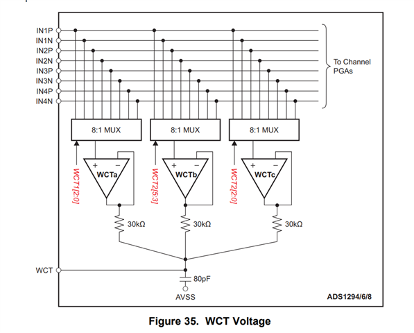
  One customer wants to know the accuracy of the 30Kohm resistor and 80pf capacitor of Figure 35. And also he also need to know the output  impedance of the three WCTa,WCTb and WCTc.

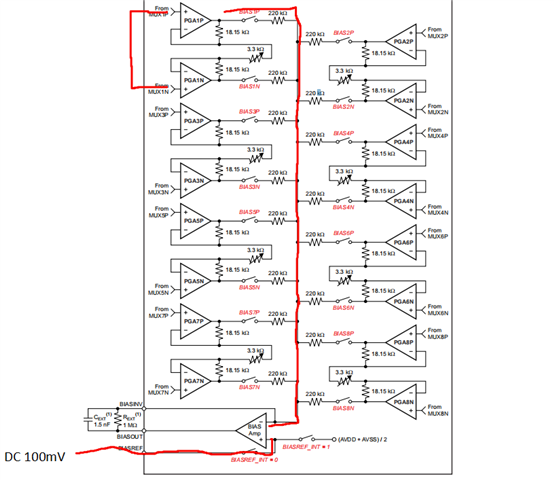
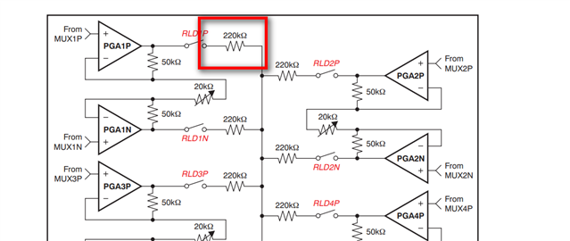
Because when he tested the BIAS function, he tested the resistor is 240ohm while the datasheet  of Figure 43 is 220Kohm . So he'd like to know the internal resistor accuracy .

Considering the specificity of the WCT, he need to improve the CMRR, and the external circuit he used the high accuracy 0.1%of component to keep the consistency. 

Best regards

Kailyn

  • Hello Kailyn, 

    We've received your ticket, please allow 48 hours to take a look and provide feedback. 

    Kind regards,
    Nick

  • Hi Nick,

    Thank you for your reply, and I am looking forward to your reply.

    Best regards

    Kailyn 

  • Hello Kailyn, 

    Given that the customer is trying to improve CMRR, there is likely another area where they could improve performance. 

    Do you have any extra details about customer schematic or use-case?

    Kind regards,
    Nick

  • Hello Nick,

    Thank your for your reply. Here  is the circuit of the customer:

    Best regards

    Kailyn 

  • Hi Kailyn, 

    I'm trying to understand how your customer measured that 240 Ohm measurement. Please ask them these questions: 

    • What were the conditions in which the 240 Ohms was measured?
    • Could the customer share their register settings? As some internal switches are closed, it will change the impedance measured.

    Thanks,
    Nick

  • Hello Kailyn, 

    I'll be closing this thread in 24 hours since it's been almost a week. If your customer gets back to you, please reply on this thread, as it will reopen the thread.

    Kind regards,
    Nick Z

  • Hi Nick,

    Our customer  also have questions about this questions.

    First, he considered how to improve CMRR with WCT function. According to his schematic, WCT output is composed with amplifier, external 30Kohm and 80pF capacitor. So the accuracy of output impedance, resistor, capacitor would caused CMRR error with design value.

    So he  asked you earlier about the 30k resistor and 80pF capacitance in Figure 35 (ADS1294 Specification), what is the error? What is the temperature coefficient? The output impedance of the WCT? These three issues are of major concern to us. Understanding these three parameters allows us to better evaluate CMRR achievement through simulation.

    As to how measure the 240Kohm, as it was test last year, I illustrated as following:

    1.turn on only the BIAS1P and connect the 220kΩ resistor in the figure to the negative input of the BIAS amplifier;
    2.turn on the BIAS external reference  BIASREF_INT=0 , input  DC 100mV; T
    3. The BIAS amplifier theoretical output value is (2200/220+1)*100mV=1100mV with an external resistance of 2200kΩ Rxt, but we measured 1005mV;
    4 Change the Rext to 220kΩ, The BIAS amplifier theoretical output value is (220/220 + 1)*100mV=200mV, but we measured it at 191 mV;
    5. Using the above method, we changed the Rxt to 1100kΩ and the measured value to 553mV;
    So, by pushing backwards  Internal 220kΩ inaccuracies were found, with an actual value of 243kΩ;
    To validate our idea in a closer way, we turn on the BIAS1P and BIAS1N so that the negative end of the BIAS amplifier is connected to half the previous resistance. We changed the Rxt to 2200kΩ and the measured value to 1910mV and calculated the typical band of 243kΩ resistance as (2200/121.5 + 1) *100=1910mV, which corresponds to the actual result. In this way, we also measured a Rext of 910kΩ, which is also satisfied.

    Best regards
    Kailyn 

  • Hello Kailyn, 

    Let me check on a couple things on my side, I'll respond within 24 hours. 

    Kind regards,
    Nick Z

  • Hi Kailyn, 

    Just to confirm, has the customer measured the 240KΩ value from physical testing, or was it all simulated? 

    Kind regards,
    Nick Z

  • Hi Nick,

    They  measured the 240KΩ value from physical testing。

    Best regards

    Kailyn

  • Hi Kailyn, 

    Is there a reason why the customer is using 100mV to test the external reference? If the customer wanted to measure biasing characteristics, I recommend they observe the behavior of the waveform using internal registers for RLD_MEAS instead of external circuitry because there will be fewer factors affecting the output, like input impedance for the external reference. 

    In the next day or two I'll do some testing and see what I get on my side using the included procedure.

    Does the customer already have this device on a board? If you could have them send over their layout, there could be something there that's affecting CMRR.

    Kind regards,
    Nick Z 

  • Hello Nick,

    I went back to the test when we tested the 1299 Bias output function and found that the bias amplifier output ratio did not match the expected design. So, we use an external reference of 100mV to verify where the problem is in the circuit (the test method is mentioned above). As to why an external 100mV reference is used, for the following reasons:

    First, if we use the internal reference to the ADS1299, which is (AVDD+AVSS)/2, our analogue supply is ±2.5V. Therefore, using the internal reference, the signal output of the bias amplifier is close to 0, which is not good for observation. Therefore, the 100mV external reference voltage is an option that allows easy observation of the bias amplifier output and does not output  saturation。

    Again, we measured the actual value of the ADS1299 internal 220k as 243k using this method. Through this phenomenon, we have doubts about the values of the internal capacitors and resistors of the diagram, are they accurate? If they are inaccurate, using the ADS1294 WCT feature can cause differential channel input to be unbalanced, causing the CMRR to not meet design expectations.

    So we only care if the ADS1294 WCT discharge output resistors 30k, and 80pF are accurate and what is their error?

    All devices are on the PCB top layer.

    Best regads

    Kailyn 

  • Hi Kailyn, 

    I'll be reviewing this, it may take some time. 

    Kind regards,
    Nick Z

  • Hi Nick,

    Thank you for your reply,  and I am  waiting for your reply.

    Best regards

    Kailyn 

  • Hi Kailyn, 

    I've sent you a couple questions via email. 

    Kind regards,
    Nick Z

  • Hi Kailyn, 

    Since it's been over a week without a response, I must assume the problem has been solved. Please reach out to me directly via email for updates on this topic. 

    Kind regards,
    Nick Z