This thread has been locked.

If you have a related question, please click the "Ask a related question" button in the top right corner. The newly created question will be automatically linked to this question.

AFE58JD32LPEVM: Capturing an Analog Input Signal With the LVDS Interface - Frequency mismatch

Part Number: AFE58JD32LPEVM
Other Parts Discussed in Thread: AFE58JD32LP

Dear TI support team,

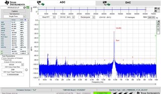
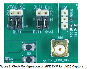
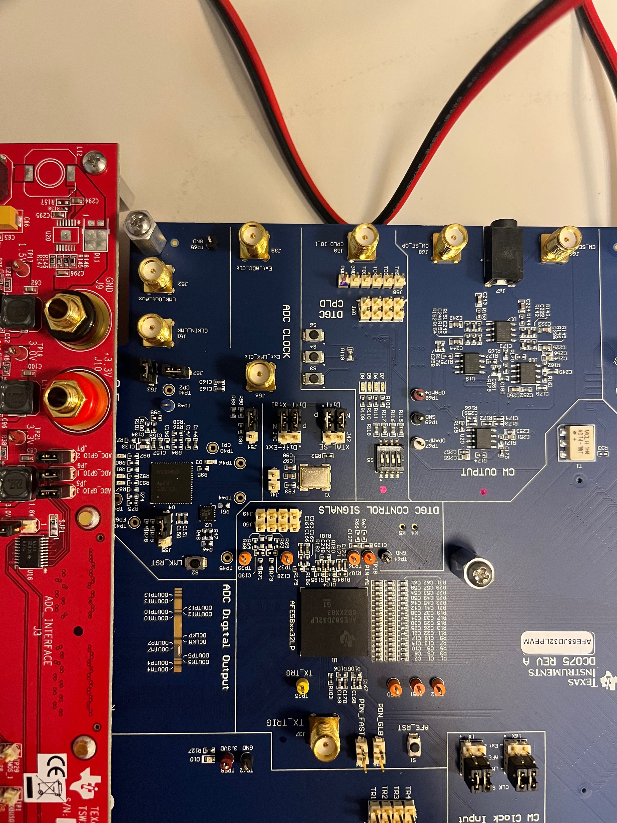
I'm setting up a system with the AFE58JD32LPEVM and TSW1400EVM following the procedure described in the user's guide SBAU326–August 2018 of the AFE58JD32LPEVM. The setup is the same described in figure 4 of the guide except for the optional external clock reference that i did not connect. I've followed the instruction for "LVDS Capture only" but instead of getting a sharp peak at 5 MHz as shown in Figure 17 at page 12, I'm getting a peak at 6.4 MHz. I attach the screenshot from the HSDC Pro showing the mentioned peak at 6.4 MHz, but if i connect my generator to a spectrum spectrum analyzer i see the peak as expected at 5 MHz. Can you help me in setting properly the system to observe the peak at 5 MHz in HSDC Pro as expected from Figure 17?


Thank you very much,

Marco Travagliati

  • Hi Marco,

    This could happen if AFE is not receiving proper ADC clock or some other source is coupling to ADC clock. Can you confirm that jumper connections on your board (J42, J40)are same as below picture ?


    Also, can you try to probe the ADC clock near the AFE and confirm that incoming clock is of 40MHz frequency ?. Please share us the probed waveform if possible.

    on R107, ADC clock can be probed by a oscilloscope.

    Regards,

    Kalyan

  • Hi Kalyan,

    my configuration was the one in the picture below.


    The signal measured between the GND and R107 is reported in the following csv.

    SDS00002.csv

    If I use the configuration you recommended I get the following error from the GUI

    and the reading on R107 is the following

    SDS00004.csv

    I found that the configuration working correctly is the one in the following picture

    and i can read in this case a 40 MHz clock reported in the following CSV on R107.

    SDS00001.csv

    I would like also to mention that on the start of the HSDC Pro, once I upload the FW of the ADC I get the following error message

    I'm running HSDC Pro 5.2 and I cannot find on your website the older versions of the HSDC recommended. How would you recommend to proceed for the SW? Can I simply neglect the warning message?

    Regarding my results, may you comment on them?

    Thank you,

    Marco

  • Hi Marco,

    Thanks for sharing the waveforms with different configurations. 

    In your initial configuration (data dump SDS00002.csv), the adc clock frequency is 31.25 MHz. That explains why you are seeing a tone at 6.4 MHz. Since in HSDC pro you set Fs to 20 MSPS, the measured fundamental tone will also get scaled accordingly. Fund = 20*5/(31.25/2) = 6.4 MHz.

    The wave you shared in the third configuration looks correct (SDS00001.csv). Please use that clock configuration for your further testing. You can ignore the HSDC pro not compatible warning. I've successfully used AFE58JD32LP EVM with HSDC Pro 5.2 in the past.

    Regards,

    Kalyan