This thread has been locked.

If you have a related question, please click the "Ask a related question" button in the top right corner. The newly created question will be automatically linked to this question.

ADS5282EVM Analog Inputs

Other Parts Discussed in Thread: ADS5282EVM, ADS5282

Hello,

I would like to ask what charasteristics the analog inputs signals should have (width and pulse hight) , to properly connect them to the ADS5282EVM ADC.

I read in the manual that -1V corresponds to the 0 digital value 0V corresponds to 2048 and 1V to 4096..

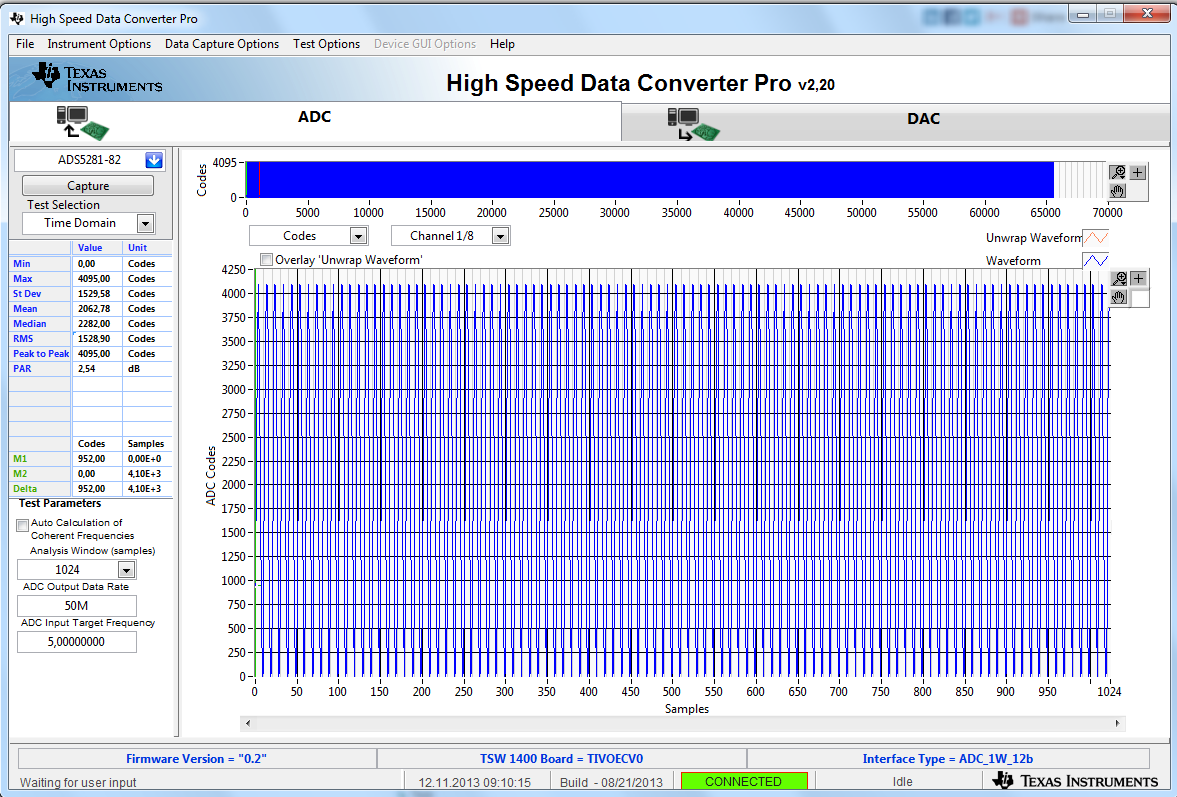
That means that if i connect a sin signal from a function generator with amplitude greater than 2Vpp the i would not see any digital samples above the 4096 value. Right?

The strange thing is that i try ADS5282 operation with different function generators  have different results...Maybe this is because of resistance output generator? I used two generators; the first has 50 ohm resistance output  and its operation is as described above for a sine wave with amplitude greater than 2Vpp. The second digitize nomally sine waves with amplitudes greater than 2Vpp. I dont know the value of its output resistance....

I would like to use the ADS5282 ADC for digitizing signals from a Position Sensitive Photomultiplier Tube (PSPMT). What should be the value of the output resistance from our custom amplification circuit? Are there any other charasteristics that our analog signals should have?

Lefteris


  • Hi,

    The ADS5282 does not care about the impedance of the source, but regardless of the source impedance you will want to terminate the signal properly with a matching impedance.  As you point out, an input voltage of -1V corresponds to an output code of all '0' and an input voltage of +1V corresponds to an output code of all '1'.   Besides holding the common mode level of the differential input to the ADC at the desired common mode voltage, that is about it.

    If you are looking at the ADS5282 EVM, it is normally set up for a single ended SMA input from a 50 ohm source, so the termination after the transformer coupling is 50 ohm differential.  If we were to install the optional second SMA for a differential input from two 50 ohm coax connections we would change the termination to 100 ohm differential.  Either way, 2V peak to peak is full scale.  When an amplifier is used instead of a trasnformer, the load resistance may be 400 ohms differential.  The ADC itself doesn't care, but at higher frequencies of interest the input impedance of the ADC itself may need to be considered as part of the proper termination value.

    Input bandwidth of the input circuit and input bandwidth of the ADC itself may attenuate higher frequencies more, meaning you may have to have a larger signal at the input of the EVM to get to full scale.  The transformers on the EVM typically have about 1dB attenuation in their pass band, but very high or very low frequencies will suffer greater attenuation, meaing you will see a smaller swing at the output codes for the same launch amplitude.  You would want to consider the frequency content of the signal you want to sample, which for a pulse or edge may mean you need to consider the slew rate of the edge to see what your required bandwidth is.  And the data converter itself will have an input bandwidth that should be listed in the datasheet.  

    impedance matching or input bandwidth may each be part of what you are seeing regarding different output range for different input signals of the same amplitude.

    Regards,

    Richard P.

  • Hello,

    I have a problem with the max. Voltage Peak to Peak with my ADS5282 EVM.

    My System is a TSW1400 and a ADS5282 EVM.

    As mentioned above is the max. Voltage peak to peak  2V with the internal reference.

    But if I plug a Signalgenerator with Output Impedance of 50 Ohm and a Voltage of 1.7 Vpp Sinus, then I get from the ADC Codes from 0 to 4096.

    Is this a configuration Problem ?


    With best regards,


    Roland


  • Hi,

    Can you turn the signal level from the signal generator down to a level that does not hit + or - full scale, and is the captured signal spectrum celan after that?   I am looking at the bill of materials for the build of the ADS5282 EVM and it looks to me like the input transformers are 1:1 ratio, but the definition of the 'footprint; of the magnetics is a part number for a 1:4 ratio transformer.  If a 1V peak to peak signal just fits under the ADC full scale, then there could be a voltage doubling in the magnetics.    Or, maybe more likely, there may be a miscommunication on fullscale definition for our input voltage.  Our full scale definition is 2.0V peak to peak, differential.  That means that each *side* of the differential signal has a 1.0V swing.   When you see 1.7V peak to peak, are you looking at the swing of the single ended signal coming into our EVM before the transformer?  Or do you see 1.7V peak to peak using a differential probe across the differential signal after the transformer?  Or do you see 1.7V peak to peak looking at one side of the differential signal after the transformer?  If it is the latter, then this would be a 3.4V peak to peak signal differential into the ADC and our ADC would clip.

    Regards,

    Richard P.

  • Hello,

    Thank you for you quick reply.

    When I turn down the level (< 1.7 Vpp) then i got smaller Values an the hit + or - are don't reached.

    I measured with an oszi, a differential signal level after the transformer of 1.7 Vpp, when I plug in a Signal with a level of 1.7 Vpp, so the transformer must be ratio of 1:1 .

    The measured sprectrum got a high peak at the plugged frequency (e.g. 5 MHz), an some small peak's at the harmonics.

    The second picture is with a level of 1.7 Vpp from the signal generator.

    With best regards,

    Roland