This thread has been locked.

If you have a related question, please click the "Ask a related question" button in the top right corner. The newly created question will be automatically linked to this question.

ADS124S08: ADC Errors occurring linearly, not a simple offset error

Part Number: ADS124S08

Our errors seem to be coming up in a progressive manner until it saturates at full scale output. We fed various voltages from 0 to 5 volts to the ADC Input.

Reference voltage 2.5V

AVDD 5V

Simple offset calibration wont suffice. 

Has this issue been faced before by anyone, or any suggestions would be appreciated.

  • Hi Shrihari,

    Welcome to the E2E forum!  Can you provide a schematic and device configuration register settings?  It would seem that perhaps the input is actually floating.  Also, using a 2.5V reference and a 5V input source will show as full-scale.  As the ADC measures relative to the reference voltage, any input that is greater than the reference voltage will appear as a full-scale reading.

    As far as the data you are showing, what does this mean?  Normally I would expect to see a value in codes representing the conversion result.  The conversion result would be an integer value, so there must be a computation of some sort taking place.  I would highly recommend just looking at the raw data coming from the ADC instead of any computation to rule out computational error.

    Best regards,

    Bob B

  • Hi Bob,

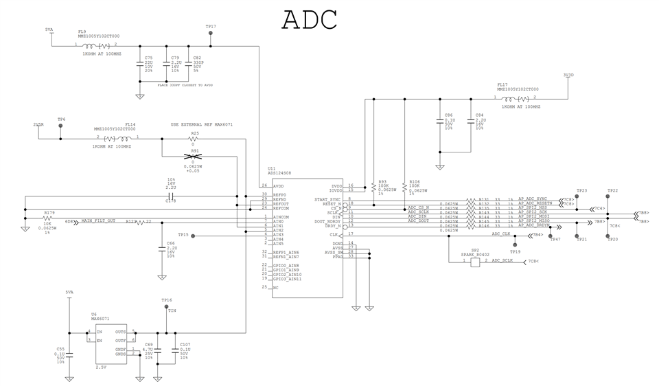
    Sharing the schematic for your reference.


    These values represent the difference between the actual value and the calculated value when we fed voltages from 0 - 5 volts to the ADC input we were monitoring.

    We have verified the code value conversions before sharing these numbers in ADC counts.

    Will be sharing the register settings as soon as possible.

    Thanks

  • Hi Shrihari,

    Thanks for the schematic.  It would appear that you intend on making a pseudo-differential measurement so that the output code at a 2.5V input is 0 and above 2.5V is a positive code result and below 2.5V is a negative code result.

    This should work fine, however I have no way of determining where the result is relative to the input voltage.  Can you show me a data table of the input voltage applied and the conversion result in raw codes.  These raw code results should be integers only and no fractional portion.  In other words I don't want to see any computation just an input voltage and the ADC code result.

    Best regards,

    Bob B

  • Hi Bob,

    Yes, that is correct. Our aim is to do exactly this. Our signal is riding on the 2.5V signal.

    Voltage fed`

    Calculated Values

    ADC Output

    Difference In Values

    5

    8388607

    8388607

    0

    4.9

    8053063.68

    8084844

    -31780.32

    4

    5033164.8

    5058065

    -24900.2

    2.5

    0

    17685

    -17685

    2

    -1677721.6

    -1663825

    -13896.6

    1

    -5033164.8

    -5025113

    -8051.8

    0

    -8388608

    -8388608

    0

    Regards

    Shrihari V

  • Hi Shrihari,

    Something is incorrect in your computation.  Also note that all data returned from the ADC is binary 2's complement 24-bit values.  Positive full-scale should be 0x7FFFFF and not negative full-scale which is 0x800000.  So in the 5V input case something is way off in your data.  The end result voltage computation is 2.5 + ADCcodes(2.5/2^23).

    Voltage fed`

    ADC Output

    ADC Output Hex

    Calculated ADC Voltage Value Computed Voltage Result

    5

    8388608

    800000

    NA

    NA

    4.9

    8053063.68

    7AE147

    2.399999

    4.899999

    4

    5033164.8

    4CCCCC

    1.499999

    3.999999

    2.5

    0

    0

    0

    2.5

    2

    -1677721.6

    FFFFE66667

    -0.499999

    2.000000

    1

    -5033164.8

    FFFFB33334

    -1.499999

    1.000000

    0

    -8388608

    FFFF800000

    -2.5

    0

    So based on the input voltage given in your data table, it would appear that the result is very close to what should be expected.  That said, maybe I'm incorrectly interpreting what you are trying to tell me.  I may be misunderstanding what you mean by calculated value and how you made your calculation.

    Best regards,

    Bob B

  • Hi Bob,

    Sorry for the confusion, I had incorrectly named the columns.

    Please take a look at the table again, have edited it correctly. You can now see the deviations.

    And yes, at 5V the calculated value must be 8388607and not 8388608.

    Regards

    Shrihari 

  • Hi Shrihari,

    Ok, so you are trying to match a theoretical value to the ADC output code.  There are several things to consider.  The first is ADC device offset which can be calibrated out using the SFOCAL command. 

    Another is the voltage used to determine the output code which is the reference.  Most likely your calculations are determined by a specific voltage of 2.5V, but often this voltage is slightly different such as 2.495V or 2.505V which can alter the output code result.  So you need to accurately determine the precise output voltage of the reference using a calibrated voltmeter with high precision such as a Keysight 3458A.  A handheld DMM is not precise enough.

    Then to accurately determine the output code you would also need to measure the input voltage precisely in the same manner as measuring the reference.  It is very rare to see an exact voltage such as 2.5V, or 1V.

    There will also be noise in the measurement.  So I would suggest several consecutive conversions averaged together.  Also consider the variation and noise of the source.

    There are other possible error as well, but most likely the error is related to the theoretical values with respect to the 'real' values.

    Best regards,

    Bob B

  • Hey Bob,

    We used the Keysight 33500B series FG to supply the voltage. Shouldn't have more than 1mV deviation.

    Also used the Keysight 34461A to measure the voltages.

    We looked at a window as well and a stream of data which was almost continuous and varying around the same values. When we saw really high deviations, we considered averaging for the same.

    Another thing we did was to use the reference voltage itself and feed the ADC input, we still got an output count of about 5000.

    Regards

    Shrihari V

  • Hi Shrihari,

    One unfortunate aspect of E2E is that you are very familiar with your testing and setup and I am not.  I still have not received the register configuration you are using.  As an example of why this is important is you have two input configurations with two possible input and reference sources.  So when you say reference I have no idea which reference and input combinations you are converting.  Also, I do not know what the precise reference voltage is that you are using.

    Second issue I have is I do not know precisely the measured input voltage values and how this relates to the output code.  Again, you are very familiar with your setup and I am not.  So you have to give me every detail of your testing for me to help you further.

    When you said you used the reference voltage to feed back into the ADC, which reference was being used, what inputs were you using and was the pseudo-differential measurement using the same voltage source?  This is not clear as there are two possible paths for input and reference.  First issue the SFOCAL to remove any ADC offset from internal components.  If you use the system monitor you can check the offset using the internal short and verify your code and that it should be close to zero.  This would be your baseline measurement.  Next measurement select AIN1 for both AINP and AINN in the MUX register.  AIN1 by your schematic is connected to the internal reference.  Turn the internal reference on and you should again see something similar to the baseline measurement close to zero.  Next repeat your input voltage test using the reference as one of the inputs.  Again you should see something close to 0.  If you do not, then there is something in your system that is causing this additional error.

    Best regards,

    Bob B