This thread has been locked.

If you have a related question, please click the "Ask a related question" button in the top right corner. The newly created question will be automatically linked to this question.

ADC32J45: Signal dependend Glitch / Noise

Part Number: ADC32J45
Other Parts Discussed in Thread: LMK04828

Hello Colleagues,

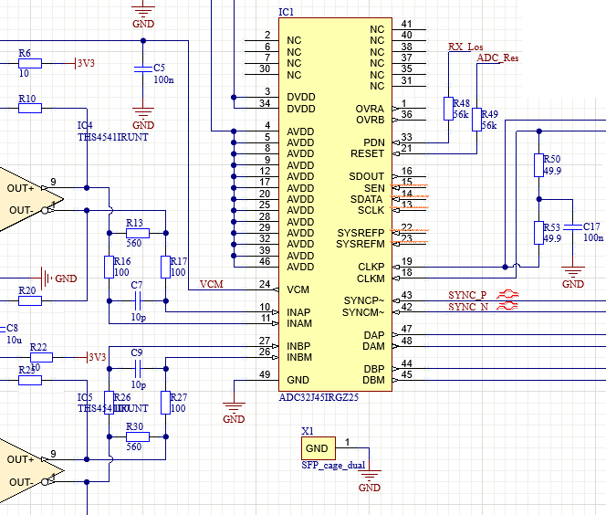
I choose the ADC32J45 for developing a measuring device in a kicker system of the XFEL (European Free-Electron X-Ray linear accelerator).

The first results show a strange noise, which seems to be dependent of the signal value. I posted a plot of the VIVADO Logic analyser, witch shows the received signal (rxdata[15:0], where the two LSBs are always zero). The conversion speed is 160MS/s, SYNC was successful, JESD data came without any errors, so the problem must be at the analog side.
The Noise peak-to-peak level is approximately 1% of the ADC range, what is not acceptable for a 14bit ADC.
At the analog input side, a THS4541IRUNT fully differential OpAmp was used, as recommended in the Eval-Schematics.


My questions: Does anybody know, what kind of noise is that (e.g. sampling-glitches) and what is the reason for it?
Could the reason be a damaged ADC?
Is there any solution, e.g. extra filtering at the ADC input pins what can prevent that kind of glitch?

Thanks in advance for answers!

Regards

Artur Boebel

Glitch / Noise in ADC Output in VIVADO

  • Hi Arthur,

    Have you tried enabling a test pattern? If not, I would recommend trying this to help isolate the issue. Let us know what you find. 

    Regards, Amy

  • Hi Amy,
    thanks for that hint... this cannot be tested, because the SPI control port is not connected / used! Yes, that sounds strange, but the ADC default configuration is (according to the datasheet), perfect for my application, and, I use fiber optics for a huge potential isolation between the ADC and FPGA (Just one Tx/Rx for clock and JESD data) and don’t wanted to add extra fibers for SPI.
    Also, I don’t really think, PRBS pattern would bring any news to solve this problem (even, if it’s not complete impossible), as there are definitely NO errors in the data output stream (JESD disparity and “not in table” even for minutes of operation).
    Regards, Artur
    ADC32J45 Schematics

  • Hi Artur,

    If SPI is not configured, can you ensure that you are doing a HW reset to the ADC first?

    Regards, Amy

  • Hi Amy,
    yes, definetly. The ADC is held in PDN and RESET by an external logic when no clock is received ("Idle-State").
    After the clock signal starts to be transmitted by the FPGA to the ADC, PDN is released and 1ms later RESET is released, to ensure, that a RESET is still applied after the wake-up time. Then, SYNC is asserted for 200µs to enable COMMA-Alignment, before valid JESD data are sent by the ADC. This procedure is tested and works fine.
    Regards, Artur

  • Hi Artur,

    I setup this EVM in our lab, and I was able to take a capture using the TI TSW14J56 the way you describe. I did have to program the onboard LMK04828 and confirm that the PLL correctly locked. What are you using for a clocking source? If you provide me with more information on your input tone, I can try to replicate that in our lab as well.

    Regards, Amy

  • Hi Amy,
    I use a Xilinx Kintex-based FPGA board and one GTX-transceiver for communicating with the ADC. The transceiver is working with 3.2 Gb/s, Tx link transmits a fixed 20bit pattern 11111111110000000000 (= 160 MHz, 50% duty) to the CLK input of the ADC and Rx receives JESD data from the ADC. The Rx port of the transceiver aligns to the coma and does the 10b8b decoding (that works very well, without bit errors). This "strange" setup is chosen because there is a SFP+ fiber optics link between the FPGA and the ADC for potential isolation. So, the clock is sourced by the FPGA internal PLL, what should be adequate related to jitter and stability.
    As described earlier, there is a clock detection logic what holds the ADC in reset state until a stable clock signal is detected.

    I really suppose, the noise is caused by an inadequate analog input circuit or any kind of ADC-sourced noise (because it is dependent of the signal value)...?
    Regards
    Artur

  • Hi Artur,

    Thank you for providing greater detail.

    We do not recommend using a clock from an FPGA board. In general, FPGA clocks have jitter in the range of 30-50 pSec, which causes the SNR of the ADC to greatly degrade. It is possible that the analog input circuit is a contributing factor to system noise. If you would like to provide us with your full schematics, but don't want to post them on this public forum, we would be happy to take this discussion offline to discuss further.

    Regards, Amy

  • Hi Artur,

    I think it would be best for us to get a full copy of your schematics. It would really help us move this forward. Also, can you describe the signal captured in the first post. Is this a sinewave at the input that you are capturing which has the bursts of noise periodically?

    Regards,

    Rob

  • Hi Amy and Rob,

    thanks for additional hints, but now, the problem is solved. The cause was a wrong byte-alignment on the receiver side. The data were wrongly combined: the MSByte of the "actual" data word was combined with the LSByte of the "previous" data word. The 14 bit ADC result is separated in two bytes, with 8 upper bits in the MSB and 6 lower bits in the LSB: rrrrrrrr|rrrrrr00. If they are combined from different ADC-results, there might be +/- 64digits "jumps" around the "edge" values, where the LSB overlaps from high values to low values.
    A huge disadvantage is, that the XILINX VIVADO GTX wizard neither gives the chance to set the byte alignment parameters in the 8B/10B settings of the transceiver, nor lets the user see, what the result will be (on the bit-layer). So I just guess that the alignment was right, but it wasn't. I finally disabled that 8B/10B decoding inside the Transceiver and included a "hand-made" 8B/10B verilog core, what gives much more flexibility to align to the right byte-sequence (first bytes of the ILA-Sequence after SYNC) - that works well and stable!
    The result is a p-p noise of much less than 0.05% of scale, what is sufficient for the application.

    Thanks again and many regards

    Artur

  • Hi Artur,

    Thank you for following up. It is helpful on our end for learning when we hear back on how the problem was solved. I am glad that to hear that everything is working. 

    Regards, Amy