This thread has been locked.

If you have a related question, please click the "Ask a related question" button in the top right corner. The newly created question will be automatically linked to this question.

DAC8771EVM:basic DAC working question

Other Parts Discussed in Thread: DAC8771EVM, DAC8771

부품 번호: DAC8771EVM

I'm sorry it's a rudimentary question.

I want to check just basic DAC work through the DAC8771EVM and DAC8771EVM Software.

Using the SM-USB-DIG as the DVDD supply.

Connecting a a12V power supply to PVDD/AVDD.

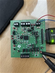
And I applied all JP positions correctly.

When SM-USB-DIG is connected to PC's USB connector and DAC8771EVM software is running,

I could check SM-USB-DIG was working well.

However, there was no output from VOUT, because maybe I couldn't deal with the GUI properly.

Please help me to check just basic DAC work through the DAC8771EVM and DAC8771EVM Software.

If I didn't do anything wrong, do I need other additional hardware or software besides DAC8771 EVM?

  • Seungmin,


    Just to be sure, the DAC8771EVM User's guide can be found here:

    http://www.ti.com/lit/ug/slau727/slau727.pdf

    When you start to operate the board, you should make sure that you have an external supply connected. You need to apply a voltage from 12 V to 36 V to the PVDD/AVDD supply at J3. At this point the current for the power supply is about 4mA. After that, then you can connect the SM-USB-DIG to the board and to the computer through the USB cable. Make sure that the SM-USB-DIG connections to the board are properly aligned (they can be plugged in mis-aligned and then the board wouldn't work). 

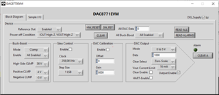
    Once the power supply and the USB are operating, then you can turn on the GUI. Here is how I have it set up:

    Here is the sequence that I run:

    1. Send HW_RESET

    2. For the buck-boost converter, I enable them all

    3. Enable the Reference Out

    4. Set the Power-off Condition to IOUT High-Z, VOUT High-Z

    5. Set the DAC output mode (here, it is the default of 0 to 5V)

    6. Enable the DAC output

    7. Set the DAC data code. Shown is 1000h

    You should be able to set up the EVM with this sequence. Let me know if you get this working.

    Joseph Wu

  • I followed the sequence as instructed, but it still doesn't working.

    also,I checked 5V on VREF_IN, 5V on DVDD and 3.3V on VPOS.

    But no signal from OUT.

    What should I do?

  • Seungmin,

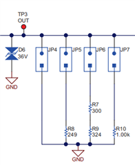
    It looks like you have the jumper for JP4 inserted in on the board. Can you please move that so that the jumper is not shorted (like the others for JP5, JP6, and JP7).

    With the jumper inserted, this shorts VOUT to GND. You can see it here in the clip from the schematic:

    If you have have this inserted you'll always read 0V. I think this is the problem, but just to check, how much current are you pulling from the supply?

    Joseph Wu

  • I'm pulling 4mA current from the supply.

    I did as you instructed (JP4 is not shorted. like JP5, JP6, JP7.). But still no output from VOUT.

    Do I need to click another button on the GUI? Such as 'SW_RST', 'CLEAR', 'READ ALL' , 'READ ALARMS', 'CLEAR A'.

    I supplied 12V to PVDD/AVDD and I checked Test Point.

    Please let me know if there is a problem.

    PVDD/AVDD = 12V
    VPOS = 2.5V
    VNEG = -15V
    VREF_IN = 5V
    DVDD = 5V
    LDAC = 0V
    ALARM = 4.9V
    CLR = 1.5V
    RESET = 5V
    MOSI = 5V
    DIG_DVDD = 5V
    SCLK = 0V
    CS = 4.7V
    MISO = 0V

  • Seungmin,

    I'm still not sure what's wrong, but most of the numbers look correct. In particular, the 4mA is about right for the supply current, and you're seeing VNEG=-15V and VREF_IN=5V. However, I would have expected to see a little higher voltage at VPOS (maybe 3 to 5V).

    Just to be sure, can you run the same test in voltage mode (output 0 - 5V range) and rerun the test? I want to see if VPOS goes to +15V. After setting the voltage output to something other than 0000h (maybe set it to 2000h).  Measure the output voltage and take a screenshot of the GUI.

    You shouldn't need to do a SW_RST, CLEAR, READ ALARMS, or CLEAR A.

    Joseph Wu

  • VPOS still measured +2.5V, and still no output from VOUT.

  • Seungmin,

    It appears that the VPOS_IN is still not getting to the pin. I don't see any jumpers in the wrong position from your original picture (except for the J4 that I mentioned). Because of that, the VPOS should have gone to 10V.

    With the board unpowered (and unconnected to the power supply) can you measure the impedance from VPOS to GND and then measure the impedance from VOUT to GND? I just want to see if there are any shorts to ground through either. 

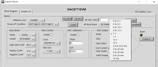
    Then when you power up the EVM again and start the GUI. Can you please check what happens when you set the DAC to the ±5V voltage output mode? I just wanted to check to see if the output can be set to any of the negative values. Even with the DAC code set to 0000h or 2000h, the output should be negative.

    Where did you get the EVM? Was it purchased from the TI Store or from a distributor?

    Joseph Wu

    Joseph Wu

  • I measured the impedance from VPOS to GND, and VOUT to GND.

    Both are not shorted.. It keeps rising at a few Mohms.

    And, I powered up the EVM again and start GUI.

    I checked -5V from VOUT. (DAC code setting = 2000h)

    But, the DAC Output Mode is set to '?V', so I don't know what I set.

    And, still measured 2.5 V from VPOS and -15.5 V from VNEG.

    Did it work correctly?

    and I selectd '0 to 5V' DAC Output Mode, but i didn't got positive voltage from VOUT.

     I received it from TI KOREA.

  • Seungmin,


    The question mark (?) comes from a problem with your computer system processing GUI font. I think it is because your default system font is a Korean font (and it's having problems with the text including the "±" sign). However, I don't think this will cause a problem in operation and I don't think this is the problem that you're seeing with the output voltage.

    At this point, I'm not sure what is wrong. While the device is responding to commands to set other things like the reference, and the VNEG voltage, it's not able to operate with VPOS. It seems this EVM is just not functioning correctly. Are you able to contact TI Korea and see if they can provide another EVM? I may be able to help you with that as well, but it may take longer to get it shipped to you.


    Joseph Wu