This thread has been locked.

If you have a related question, please click the "Ask a related question" button in the top right corner. The newly created question will be automatically linked to this question.

ADS131E08EVM-PDK: ADS131E08 front-end board's power supply

Part Number: ADS131E08EVM-PDK
Other Parts Discussed in Thread: ADS131E08

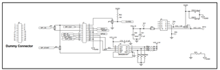
I have an ADS131E08 EVM board in my hand,but I want to use the front-end board alone. 

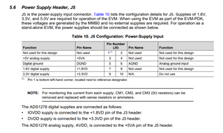
I measured that J5.3 was 5V, J5.7 was 1.8V and J5.9 was 3.3V on J5 of MMB0, so I provided the voltage to the front-end board. (MMB0 is connected to front-end through J5)

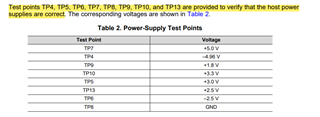
But the voltage data I measured in the power-supply Test Points of the front-end board is wrong.

So I would like to ask how to correctly supply voltage to front-end board.

  • Hello Zhen,

    You just want to use the ADS131E08EVM without the MMB0, correct? 

    J1, J2, and J3 are the connectors that transfer power from the MMB0 to the ADS131E08EVM. It looks like J3 actually gives power where J2 is not connected and J1 holds SPI, the GPIOs, and some interface to the EEPROM.

    Feel free to click on the picture if it seems blurry. J3 seems to provide VCC_1.8V (TP9), VCC_3.3V (TP10) and VCC_5V (TP7) so you would need at least the 5V. Then, depending on your desired DVDD voltage, you'd provide 3.3V to TP10 or 1.8V to TP9.

    TP5, TP4, TP13, and TP6 are derived from VCC_5v, so if you provided 5V then you should be fine for these. 

    Best,

    -Cole

    Edit: link the MMB0 schematic if you are interested: https://e2e.ti.com/support/data-converters-group/data-converters/f/data-converters-forum/775258/faq-what-documentation-is-available-for-the-mmb0 

  • This ADS131E08EVM is the same as MMB0 of ADS1278EVM.

    Then I Supply Power according to the Power Supply Header in User's Guide of 1278, but I cannot detect the corresponding voltage at Test Points.

  • Hello Zhen,

    I'm still not sure what your question is at this point. Can you please clarify if needed?

    Yes, the MMB0 is the same as the one used with the ADS1278EVM. That screenshot says if you're using the MMB0 with the ADS1278EVM (or with the ADS131E08EVM), then you don't need to provide the 5V, 1.8V, or 3.3V--"No External Supplies required" is shown in that user guide. The standalone operation, where no MMB0 is used, you need to apply the external voltages as I have outlines above (or to J5 in the case of the ADS1278EVM).

    The thing that might be confusing is that if you are using MMB0 with the ADS131E08EVM, you should try connecting to the GUI for the voltages to turn on, however, I assumed you wanted to just use the ADS131E08EVM without the MMB0.

    Best,

    -Cole

  • First, I want to use the ADS13E08EVM independently, so I need to power it.

    Second, I Power EVM according to the way described in the Power Supply Header,J5.3 is 5V, J5.7 is 1.8V, J5.9 is 3.3V, J5.5 is DGND, and J5.6 is AGND.

    Thirdly, according to the description of power-supply Test Points, when I Supply Power to EVM, I can detect the corresponding voltage in Test Points. But all the voltage I measured was 0 volts.

  • Hello Zhen,

    Apologizes for the delay.

    I think the reason we are getting confused is that J5.x does not exist on the ADS131E08EVM (its on the MMB0) so applying 5V to J5.3 does not mean anything in context of the ADS131E08EVM. If you were to instead supply 5V to TP7 on the ADS131E08EVM, it would make sense. So, if you were applying 5V to TP7 and you measured the voltage on TP7 and saw 0V, that would mean your power supply is not working as expected. Is the power supply exceeding a current limit so you can't measure the voltage there? If you use a DMM and do an impedance test between TP7 and AGND, does it read back 0 ohms?

    Best,

    -Cole