A related question is a question created from another question. When the related question is created, it will be automatically linked to the original question.
If you have a related question, please click the "Ask a related question" button in the top right corner. The newly created question will be automatically linked to this question.
Thanks your support. Yes, customer got an issue during developing their system.
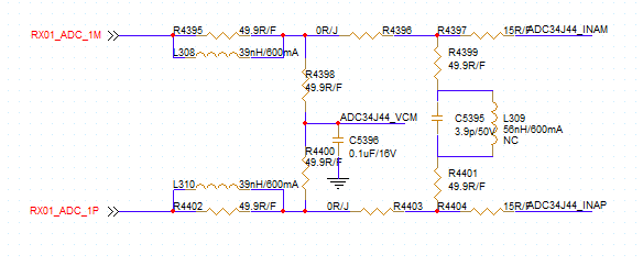
As the below picture shown is the impendence circuit from DVGA to ADC34J44, Customer find the ADC starts being saturated when input=0dbm, they think it won't be saturated until input to 7dbm based on theory analysis for this impendence circuit.
So do you think if this circuit will impact saturated power for ADC? and can you give some advice or insight for this issue?
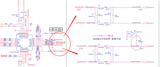
Can the customer give me their full schematic from DVGA (PN?) to ADC? I am confused on what input network they are using now. I see two pictures shown? Which one should I review?
Are they putting 0dBm at the input of the DVGA or are they saying 0dBm at the output of the DVGA?
What analog input frequency are they using for this test?
To test if the DVGA has over-ranged the ADC, You will need a way to look at the output of the ADC. Can you do that? Can you reliably capture the ADC data?
If you can, you can look at the code output, the time domain output or the FFT output to see if the input is saturating/over-ranging the converter.
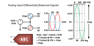
One other way to check this is using an oscope, you can probe at the analog input pins of the ADC, after C171/2 for example, and check the signal levels that way. Each leg can only tolerate +/-500mV around 1VDC. Or 0.5V to 1.5V. If the signal is bigger, you are saturating the converter. Attached is a picture to illustrate.
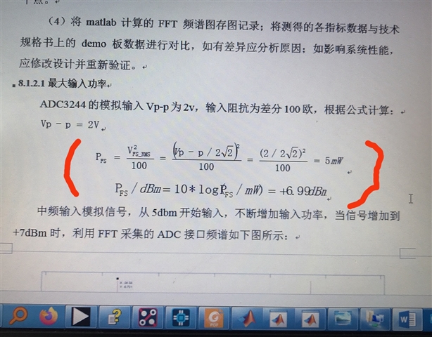
The input fullscale of the ADC is 2Vpp with an input DC common mode voltage of 1V.