


Hello I two problems using this ADC. First, the last data bits coming from the SPI are not stable, and second, the rest of bits doesn't really represent the input value.
The ADC has been soldered in a VSSOP to DIL adapter and it is tested in a breadboard.
I've added a 1uF 0402 SMD decoupling capacitor to AVDD and DVDD directly in the VSSOP adapter and also a 10uF capacitor to the REF input. There are some more capacitors in the breadboard.
AVDD and DVDD are powered from a 3.3V LDO and REF is connected to a 3V reference voltage IC. This voltage is stable.
I've been testing it with different configurations for the differential input :
- Applying some floating voltage from 0 to 3V directly to these inputs.
- Connecting AINP to GND and applying a positive and negative voltage between AINP and AINM.
- Using a differential amplifier with 1.5V common reference so the output differential voltage goes around this value.
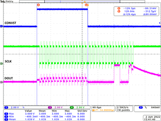
In this capture I've directly generated the signals as similar as possible as in the datasheet, for a 3-Wire configuration (DIN connected to 3.3V DVDD and AVDD), but there is always this strange behavior with last DOUT bits:
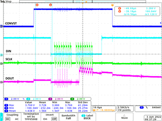
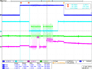
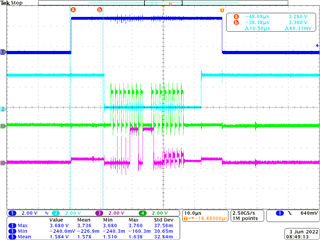
Here I use the SPI of the MCU to generate the SCLK and read the DOUT data, and the DIN and CONVST signals are generated as GPIOS AINM connected to GND and 1V in AINP. (4-Wire configuration).

I've tested with two ADS8867IDGS specimens and also with a ADS8887IDGS one.
Hope you could give me some light in this issue as I don't really know what's going on.
Thanks in advance and best regards,
Juan

