- Ask a related questionWhat is a related question?A related question is a question created from another question. When the related question is created, it will be automatically linked to the original question.
Dear Sir or Madam,
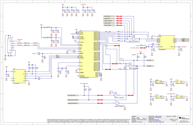
For some time now we have owned an ADC3662EVM as a reference for recording sensor data. Now we have thought about the structure. However, we have not found a circuit diagram for this module. Is there a circuit diagram for this eval board or can this be made available? In particular, the circuits between analogue inputs and adc are relevant for us.
If you need further informations please feel free to contact me.
Many thanks in advance.
Quirin