Part Number: ADC09DJ1300
Other Parts Discussed in Thread: ADC09QJ1300
Hi team,
Questions from one of our customers:
1. ADC09QJ1300 test data

@JMODE2 Quad Channel 1Ghz
CH1 sequence is correct but missing number, only 0~31, not 0~255; CH2~ch4 part data position is changed.
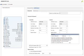
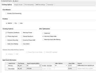
2. JESD204B phy config
3. JESD204B config


- FPGA project
Top

system
clk_wiz_inst0

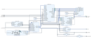
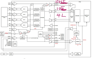
5. Hardware topology diagram
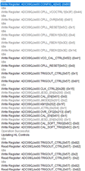
6. ADC jesd configuration code
#include "xparameters.h"
#include "xspi.h" /* SPI device driver */
#include "xstatus.h"
#include "stdio.h"
#include "xgpiops.h"
XSpi SpiInstance;
u8 adc_reg[50][3] =
{
//0
{0x00, 0x00, 0xb0},//reset
{0x00, 0x02, 0x00},//nomal /powerdown 00 03
{0x80, 0x0c, 0x00},//VENDOR_ID 2byte
{0x82, 0x70, 0x00},//VENDOR_ID 2byte
//4
{0x00, 0x29, 0xec},//CLK_CTRL0~2
{0x00, 0x2a, 0x00},//SYSREF_INVERTED
{0x00, 0x2b, 0x15},
//7
{0x00, 0x30, 0x00},//FS_RANGE L
{0x00, 0x31, 0xa0},//FS_RANGE H
//9
{0x00, 0x3d, 0x05},//CPLL_FBDIV1
{0x00, 0x3e, 0x14},//CPLL_FBDIV2
{0x00, 0x3f, 0x4a},//CPLL_VCOCTRL1
//12
{0x00, 0x57, 0x82},//TRIGOUT_CTRL
{0x00, 0x58, 0x83},//CPLL_OVR
//14
{0x80, 0x59, 0x00},//VCO_FREQ_TRIM read
//15
{0x00, 0x5c, 0x00},//CPLL_RESET
{0x00, 0x5d, 0x41},//VCO_CAL_CTRL
{0x80, 0x5e, 0x00},//VCO_CAL_STATUS
//18
{0x00, 0x61, 0x01},//CAL_EN
{0x00, 0x62, 0x0a},//CAL_CFG0 background
{0x00, 0x65, 0x05},//CAL_CFG1 OSREF DC-coupled
//21
{0x80, 0x6a, 0x00},//CAL_STATUS
{0x00, 0x6b, 0x00},//CAL_PIN_CFG CAL_SOFT_TRIG
{0x00, 0x6c, 0x01},//CAL_SOFT_TRIG
//24
{0x02, 0x00, 0x01},//JESD_EN
{0x02, 0x01, 0x02},//JMODE
{0x02, 0x02, 0x1f},//KM1
//27
{0x02, 0x04, 0x00},//singed Scrambler
{0x82, 0x08, 0x00},//JESD_STATUS
//29
{0x82, 0x70, 0x00},//INIT_STATUS
//30
{0x02, 0x03, 0x01},//JCTRL
{0x02, 0x05, 0x00},//test 15: Clock test pattern (0x00FF)
{0x02, 0x07, 0x02},//mode k28.5
//33
{0x02, 0x08, 0x03},//single mode
{0x00, 0x48, 0x00},//SER_PE
//35
{0x00, 0x37, 0x46},//LP1
{0x02, 0x9a, 0x06},//LP1
{0x02, 0x9b, 0x00},//LP1
{0x02, 0x9c, 0x14},//LP1
//39
{0x00, 0x3c, 0x00},// PLLREFO_CTRL
};
XGpioPs Gpio; /* The driver instance for GPIO Device. */
#define GPIO_PIN_0 78
#define GPIO_PIN_1 79
u8 spi_sendbuf[8] = {0x00, 0x00, 0xb0};
u8 spi_recvbuf[8] = {0, };
void InitADC(void)
{
XSpi *SpiInstancePtr = &SpiInstance;
XSpi_Config *ConfigPtr;
int Status;
ConfigPtr = XSpi_LookupConfig(XPAR_SPI_0_DEVICE_ID);
if (ConfigPtr == NULL) {
return XST_FAILURE;
}
Status = XSpi_CfgInitialize(SpiInstancePtr, ConfigPtr,
ConfigPtr->BaseAddress);
if (Status != XST_SUCCESS) {
return XST_FAILURE;
}
Status = XSpi_SetOptions(SpiInstancePtr, XSP_MASTER_OPTION);
if (Status != XST_SUCCESS) {
return XST_FAILURE;
}
/*
* Start the SPI driver so that the device is enabled.
*/
XSpi_Start(SpiInstancePtr);
XSpi_IntrGlobalDisable(SpiInstancePtr);
//step1 SOFT_RESET read NIT_STATUS VENDOR_ID
XSpi_SetSlaveSelect(&SpiInstance, 0x01);
XSpi_Transfer(&SpiInstance, &adc_reg[0], spi_recvbuf, 3);
usleep(5000);
spi_recvbuf[2] = 0;
while(spi_recvbuf[2] != 0x01)
{
XSpi_SetSlaveSelect(&SpiInstance, 0x01);
XSpi_Transfer(&SpiInstance, &adc_reg[3], spi_recvbuf, 3);
}
XSpi_SetSlaveSelect(&SpiInstance, 0x01);
XSpi_Transfer(&SpiInstance, &adc_reg[2], spi_recvbuf, 4);
if ((spi_recvbuf[2] != 0x51) | (spi_recvbuf[3] != 0x04))
{
xil_printf("Read adc id error!\n\r");
return;
}
//step2 Program the C-PLL
adc_reg[15][2] = 0x01;
XSpi_SetSlaveSelect(&SpiInstance, 0x01);
XSpi_Transfer(&SpiInstance, &adc_reg[15], spi_recvbuf, 3);//CPLL_RESET
usleep(5000);
XSpi_SetSlaveSelect(&SpiInstance, 0x01);
XSpi_Transfer(&SpiInstance, &adc_reg[11], spi_recvbuf, 3);// VCO_BIAS
XSpi_SetSlaveSelect(&SpiInstance, 0x01);
XSpi_Transfer(&SpiInstance, &adc_reg[9], spi_recvbuf, 3);//PLL_P_DIV, PLL_V_DIV and PLL_N_DIV
XSpi_SetSlaveSelect(&SpiInstance, 0x01);
XSpi_Transfer(&SpiInstance, &adc_reg[10], spi_recvbuf, 3);//PLL_P_DIV, PLL_V_DIV and PLL_N_DIV
XSpi_SetSlaveSelect(&SpiInstance, 0x01);
XSpi_Transfer(&SpiInstance, &adc_reg[16], spi_recvbuf, 3);// VCO_CAL_EN
usleep(5000);
adc_reg[15][2] = 0x00;
XSpi_SetSlaveSelect(&SpiInstance, 0x01);
XSpi_Transfer(&SpiInstance, &adc_reg[15], spi_recvbuf, 3);//Enable CPLL
//step3 stop JESD204 Calibration
adc_reg[24][2] = 0x00;
XSpi_SetSlaveSelect(&SpiInstance, 0x01);
XSpi_Transfer(&SpiInstance, &adc_reg[24], spi_recvbuf, 3);//JESD_EN = 0
adc_reg[18][2] = 0x00;
XSpi_SetSlaveSelect(&SpiInstance, 0x01);
XSpi_Transfer(&SpiInstance, &adc_reg[18], spi_recvbuf, 3);////CAL_EN = 0
// XSpi_SetSlaveSelect(&SpiInstance, 0x01);
// XSpi_Transfer(&SpiInstance, &adc_reg[39], spi_recvbuf, 3);// PLLREFO_CTRL
//
// XSpi_SetSlaveSelect(&SpiInstance, 0x01);
// XSpi_Transfer(&SpiInstance, &adc_reg[34], spi_recvbuf, 3);// SER_PE
//
// XSpi_SetSlaveSelect(&SpiInstance, 0x01);
// XSpi_Transfer(&SpiInstance, &adc_reg[35], spi_recvbuf, 3);//LP1
//
// XSpi_SetSlaveSelect(&SpiInstance, 0x01);
// XSpi_Transfer(&SpiInstance, &adc_reg[36], spi_recvbuf, 3);//LP2
//
// XSpi_SetSlaveSelect(&SpiInstance, 0x01);
// XSpi_Transfer(&SpiInstance, &adc_reg[37], spi_recvbuf, 3);//LP3
//
// XSpi_SetSlaveSelect(&SpiInstance, 0x01);
// XSpi_Transfer(&SpiInstance, &adc_reg[38], spi_recvbuf, 3);//LP4
//setp4 JMODE KM1
XSpi_SetSlaveSelect(&SpiInstance, 0x01);
XSpi_Transfer(&SpiInstance, &adc_reg[25], spi_recvbuf, 3);//JMODE
XSpi_SetSlaveSelect(&SpiInstance, 0x01);
XSpi_Transfer(&SpiInstance, &adc_reg[31], spi_recvbuf, 3);//test
XSpi_SetSlaveSelect(&SpiInstance, 0x01);
XSpi_Transfer(&SpiInstance, &adc_reg[32], spi_recvbuf, 3);//k28.5
XSpi_SetSlaveSelect(&SpiInstance, 0x01);
XSpi_Transfer(&SpiInstance, &adc_reg[26], spi_recvbuf, 3);//KM1
//setp5 SYNC_SEL SYSREF
XSpi_SetSlaveSelect(&SpiInstance, 0x01);
XSpi_Transfer(&SpiInstance, &adc_reg[27], spi_recvbuf, 3);//SYNCSE
adc_reg[4][2] = 0xa0;
XSpi_SetSlaveSelect(&SpiInstance, 0x01);
XSpi_Transfer(&SpiInstance,&adc_reg[4],spi_recvbuf,3);
//CLK_CTRL0//SYSREF_RECV_EN
usleep(1);
adc_reg[4][2] = 0xe0;
XSpi_SetSlaveSelect(&SpiInstance, 0x01);
XSpi_Transfer(&SpiInstance,&adc_reg[4],spi_recvbuf,3);
//CLK_CTRL0//SYSREF_PROC_EN
XSpi_SetSlaveSelect(&SpiInstance, 0x01);
XSpi_Transfer(&SpiInstance, &adc_reg[5], spi_recvbuf, 3);//CLK_CTRL1
XSpi_SetSlaveSelect(&SpiInstance, 0x01);
XSpi_Transfer(&SpiInstance, &adc_reg[6], spi_recvbuf, 3);//CLK_CTRL2
//step6 foreground or background calibration modes and offset
// XSpi_SetSlaveSelect(&SpiInstance, 0x01);
// XSpi_Transfer(&SpiInstance, &adc_reg[19], spi_recvbuf, 3);// CAL_CFG0 background
//
// XSpi_SetSlaveSelect(&SpiInstance, 0x01);
// XSpi_Transfer(&SpiInstance, &adc_reg[20], spi_recvbuf, 3);// CAL_CFG1 DC-coupled
//step7 TRIGOUT_CTRL
XSpi_SetSlaveSelect(&SpiInstance, 0x01);
XSpi_Transfer(&SpiInstance, &adc_reg[12], spi_recvbuf, 3);
XSpi_SetSlaveSelect(&SpiInstance, 0x01);
XSpi_Transfer(&SpiInstance, &adc_reg[35], spi_recvbuf, 3);
XSpi_SetSlaveSelect(&SpiInstance, 0x01);
XSpi_Transfer(&SpiInstance, &adc_reg[36], spi_recvbuf, 3);
XSpi_SetSlaveSelect(&SpiInstance, 0x01);
XSpi_Transfer(&SpiInstance, &adc_reg[37], spi_recvbuf, 3);
XSpi_SetSlaveSelect(&SpiInstance, 0x01);
XSpi_Transfer(&SpiInstance, &adc_reg[38], spi_recvbuf, 3);
// MB_Sleep(5);
//step8 read VCO_CAL_DONE CPLL_LOCKED
// XSpi_SetSlaveSelect(&SpiInstance, 0x01);
// XSpi_Transfer(&SpiInstance, &adc_reg[17], spi_recvbuf, 3);
//
// XSpi_SetSlaveSelect(&SpiInstance, 0x01);
// XSpi_Transfer(&SpiInstance, &adc_reg[27], spi_recvbuf, 3);
//
// XSpi_SetSlaveSelect(&SpiInstance, 0x01);
// XSpi_Transfer(&SpiInstance, &adc_reg[28], spi_recvbuf, 3);
//
// XSpi_SetSlaveSelect(&SpiInstance, 0x01);
// XSpi_Transfer(&SpiInstance, &adc_reg[31], spi_recvbuf, 3);
//
// XSpi_SetSlaveSelect(&SpiInstance, 0x01);
// XSpi_Transfer(&SpiInstance, &adc_reg[32], spi_recvbuf, 3);
//
// XSpi_SetSlaveSelect(&SpiInstance, 0x01);
// XSpi_Transfer(&SpiInstance, &adc_reg[33], spi_recvbuf, 3);
//step9 CAL_EN JESD_EN
adc_reg[18][2] = 0x01;
XSpi_SetSlaveSelect(&SpiInstance, 0x01);
XSpi_Transfer(&SpiInstance, &adc_reg[18], spi_recvbuf, 3);////CAL_EN = 1
// MB_Sleep(10);
adc_reg[24][2] = 0x01;
XSpi_SetSlaveSelect(&SpiInstance, 0x01);
XSpi_Transfer(&SpiInstance, &adc_reg[24], spi_recvbuf, 3);//JESD_EN = 1
//step10 Trigger a foreground calibration
// adc_reg[23][2] = 0;
// XSpi_SetSlaveSelect(&SpiInstance, 0x01);
// XSpi_Transfer(&SpiInstance, &adc_reg[23], spi_recvbuf, 3);
//
// MB_Sleep(1);
//
// adc_reg[23][2] = 1;
// XSpi_SetSlaveSelect(&SpiInstance, 0x01);
// XSpi_Transfer(&SpiInstance, &adc_reg[23], spi_recvbuf, 3);
// MB_Sleep(1);
// sleep(5);
// XSpi_SetSlaveSelect(&SpiInstance, 0x01);
// XSpi_Transfer(&SpiInstance, &adc_reg[21], spi_recvbuf, 3);
// XGpio_SetDataDirection(&Gpio1, CHANNEL1, WRITE8);
// XGpio_DiscreteWrite(&Gpio1, CHANNEL1, 0x01);
// XGpio_DiscreteWrite(&Gpio1, CHANNEL1, 0x00);
}
/*****************************************************************************/
/**
*
* Main function.
*
* @param None
*
* @return XST_FAILURE.
*
* @note Infinite loop so returning is a failure!
*
******************************************************************************/
//XPAR_JESD204_PHY_0_BASEADDR
//XPAR_JESD204_0_BASEADDR
int main(void)
{
int Status;
XGpioPs_Config *ConfigPtr;
/* Initialize the GPIO driver. */
ConfigPtr = XGpioPs_LookupConfig(XPAR_XGPIOPS_0_DEVICE_ID);
Status = XGpioPs_CfgInitialize(&Gpio, ConfigPtr,
ConfigPtr->BaseAddr);
if (Status != XST_SUCCESS) {
return XST_FAILURE;
}
InitADC();//star adc clk
sleep(2);
Xil_Out32(XPAR_JESD204_PHY_0_BASEADDR + 0x604, 0x0f);//RXPOLARITY
Xil_Out32(XPAR_JESD204_PHY_0_BASEADDR + 0x420, 1);//tx reset phy
Xil_Out32(XPAR_JESD204_PHY_0_BASEADDR + 0x424, 1);//reset phy
usleep(1000);
Xil_Out32(XPAR_JESD204_PHY_0_BASEADDR + 0x424, 0);//reset phy
usleep(1000);
Xil_Out32(XPAR_JESD204_0_BASEADDR + 0x004, 2);//reset
usleep(1000);
Xil_Out32(XPAR_JESD204_0_BASEADDR + 0x004, 0);//reset
usleep(100000);
//sysref_en
XGpioPs_SetOutputEnablePin(&Gpio, GPIO_PIN_1, 1);
XGpioPs_SetDirectionPin(&Gpio, GPIO_PIN_1, 1);
XGpioPs_WritePin(&Gpio, GPIO_PIN_1, 1);
usleep(40);
XGpioPs_WritePin(&Gpio, GPIO_PIN_1, 0);
usleep(10);
return 0;
}
Best Regards,
Amy Luo