This thread has been locked.

If you have a related question, please click the "Ask a related question" button in the top right corner. The newly created question will be automatically linked to this question.

ADS1298ECGFE-PDK: Power Supply issue

Part Number: ADS1298ECGFE-PDK
Other Parts Discussed in Thread: ADS1298,

Hi Team,

Good day! I am postng this in behalf of the customer. Kindly check the full details below.

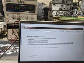
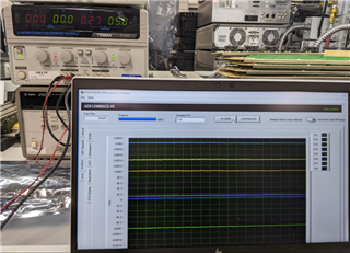
We are curently working with the "ADS1298 ECG" evaluation board.

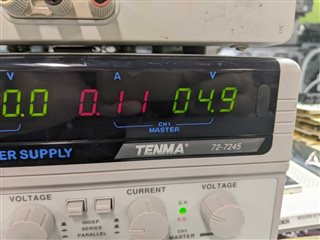
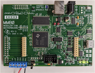
When we hook the "mmb0 modular ewm motherboard" to an Laboratory Power Supply, with 5 volts, it is drawing +3 amps, at around 4 volts, it is basically capping our Power Supply.

The LED's on the boards are turning on, but some components reaches temperatures above 90 degrees celcius, so we turned it off.

We are sure that it's not normal for the motherboard to be drawing 3 amps at any time.

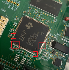
We want so ensure that we hooked it up correctly, before we return the product to you, so we have included some pictures.

sn_customerservice_case_144fb3a5473b055068ef7a51e36d431c_attachments.zip

  • Hi,

    I tested on my end -

    Without the daughter board(i.e. MMB0 motherboard only, no ADS1298EVM connected) -

    noticed the LEDs light up.

    The current should be around 0.11A more or less -

    With daughter board connected and connected to computer and GUI launched and recognized the boards, current is around 0.26~0.3A

    During acquiring - current at least around 0.27A 

    Did customer remove J12 jumper before supply J13A?

    Can customer probe or check the connectivity of the U5's Pin2 or and Pin4 with respect to gnd? I suspect something damage on customer's MMB0. 

    Thanks 

  • Without the daughter board(i.e. MMB0 motherboard only, no ADS1298EVM connected) -

    noticed the LEDs light up

    MMB0 5V from benchtop power supply

  • Hello ChienChun Yang.

    Here is our customer's response below. 

    The EVM did not come with a wall outlet power adapter, or any form of external power supply.

    That is why we are using a Laboratory Power-Supply with unipolar supply.
    We hooked it up by following this guide:

    chrome-extension://efaidnbmnnnibpcajpcglclefindmkaj/www.ti.com/.../slau262d.pdf

    Section:
    "7.3.2 Connecting a Laboratory Power Supply"

    In addition to that, we are gonna test the pins with respect to GND, and reply back with the voltages as comparison.
    I think we shorted the J13B and not the J13A, so we are gonna try that.
    We did disconnect the J12 jumper.

    We are testing the board without the ADS.

    Best regards,

    Jonathan

  • Hi,

    The document referred is not for ADS1298EVM and the MMB0 board revision in that document is old; it was revision C. Is customer using a MMB0 RevC or RevD?

    Yes, please double check the trace/circuits around U5's Pin2 or and Pin4 with respect to gnd. Probably somewhere is shorted.

    Thanks

  • Hi ChienChun Yang,

    As per our cusotmer, thank you for your patience and help!

    The board is a:
    REV D, 2009 MMBØ, modular EVM Motherboard


    I just tested the all of the pins on the DMOS "U5", first i tested the continuity on all pins with respect to GND (without power supply):
    1: 97.6k (Vin)
    2: 97.6k (Vout)
    3: 00.0 (GND)
    4: 6.9Mega (NR/Adjust)
    5: 97.6k (Enable)

    Then i tested the board with 5 volts unipolar (setup in the same way as in the picture you send). I can get a maximum of 4 volts at 3.2 Amps, because my lab power supply i capping.
    I only turn it on for 1 sec to note the voltage, and then turn it of again.

    1: 00.3mV (Vin)
    2: 00.3mV (Vout)
    3: 00.3mV (GND)
    4: 50-100 mV (NR/Adjust) (not changing when i turn on supply)
    5: 00.3mV (Enable)

    Important:

    "While closely looking at the board, i noticed that multiple of the legs on the DSP TMS320 "U20" are shorted with a bit of tin, in 4 different places." We tried everything with some of your experts and he got the same enquipment as us and he could turn it on and off.. 

    If you can send us a new one(ADS1298ECGFE-PDK) while we are sending it back to you guys that would be PERFECTO! "

    Here is the attached image of the device

    Could you confirm if we can replace this ADS1298ECGFE-PDK? Thank you

    Best regards,

    Jonathan

  • Hi Jonathan and Customer,

    Sorry to see the excessive soldering causing the apparent shorts and possible damage to the board.
    If not purchased directly from TI, the customer will need to contact the vendor/retailer where they purchased the board from and ask for refund or replacement.

    Thanks

  • Hi  ChienChun,

    Thank you for the response. I will take it from here and inform our cusotmer. 

    Best regards,

    Jonathan