This thread has been locked.

If you have a related question, please click the "Ask a related question" button in the top right corner. The newly created question will be automatically linked to this question.

ADS131E08: data conversion error

Part Number: ADS131E08
Other Parts Discussed in Thread: ADS131A04, , , ADS131M08

Hello!

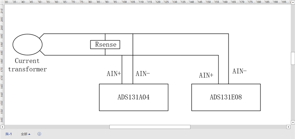
I'm using ADS131E08 & ADS131A04 to evaluate a periodically changed voltage input.

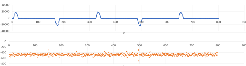
When two ADC board worked alone, I got different shape of wave. And oscillometer shows the A04's conversion is correct. But when they connect parallelly to the input, both ADC converte correctly. And when A04 is power off, E08 become wrong again.

This is so strange! But when I degisned a new board with ADS131E08S, the same situation occurs.

Below is result of two ADC's conversion. Thanks!

  • Hi Zijizn!

    Welcome to our e2e forum!  Can you provide a block diagram or schematic showing how you have the ADS131E08 and ADS131A04 connected together?

  • Hi Tom!

    Thanks for your reply.

    A drift shows as below:  (ADS131A04 and ADS131E08 are supposed to have same input)

    I use the divice to monitor current of a LED lamp. And I found an intereting thing while increasing the current of the lamp. The lost wave come back a little when ADS131E08 worked alone. But still, when ADS131E08 and ADS131A04 connected parallel, the wave become normal again. What's more, the lost wave will become positive, when I exchange the input of AIN+ and AIN-.

    The strange things happen only when I use ADS131E08 and ADS131E08S, and the ADS131A04, ADE7763 from TI and AD7768 from ADI worked well. I'm wandering whether I need to try ADS131M08.

  • Hi Zijian,

    What hardware are you using?  Do you have our EVM's for the ADS131E08 and ADS131A04 or is this setup your own custom hardware?

  • Hi Tom,

    Both two chip are my own custom hardware, their schematics shows as below (sorry for the resolution). The MCU I use is ESP32.

    ADS131A04

    ADS131E08

    Recently, I find that although I can config each register correctly, like CONNFIG1 for sample rate or CONFIG2 to use internal test signal. But when I try to read the register from the chip, I get nothing or wrong value.

    Will this affect correctness of the conversion? But why does ADS131E08 work correctly when two different ADC connect parallelly?

    And this situation happens when I implement a new design with ADS131E08S.

  • Hi Zijian,

    Looking at your schematics, I don't see where you are referencing the input to ground, which is probably why you see the apparent offset in the conversion results in the ADS131E08 alone plot and at the moment, I don't have a good explanation why that clears up when paralleling with the ADS131A04.  Can you split your RSENSE in two and connect the inputs as shown in Figure 104 from the ADS131A04 datasheet or Figure 9-7 in the ADS131M08 datasheet?  For the register read/write question, can you grab screen shots of your communication lines (/CS, SCLK, SDIN, SDO)?

  • Hi Tom,

    Thanks for your reply, I've tried your suggestion to split RSENSE on breadboard, but it's not work. And I'll try it on my new ADS131M08's design to see whether it works.

    I can grab the screen shots of these SPI communication lines. In fact, all these data are grabed by logic Analyzer.

  • Hi Tom,

    Thanks for your advice! Recently I reconnected these RSENSEs again, and I find ADS131E08 finally works well. E08 can capture both positive and negative waves when it works alone.

    But there are still some differences. When the current is at low-level,  the data measured as below (the orange points are ADS131E08 works alone, and the blue points are ADS131E08 paralleling with ADS131A04),we can see E08 cannot capture low input while working alone.


    But when the current is higher, ADS131E08 alone can capture the signals, but the max value are lower than paralleling with ADS131A04(the points are manually aligned), and It will lose some details while the current is low:

  • Hi Zijian,

    Can you provide a picture of your setup? And perhaps a complete schematic of your analog front end?  How are you able to connect and disconnect the ADS131A04 and ADS131E08S?  I suspect the difference you are seeing may be due to the differences in the input impedance between the two parts.

  • Hi Zijian!

    Have you made any further progress on this issue?