This thread has been locked.

If you have a related question, please click the "Ask a related question" button in the top right corner. The newly created question will be automatically linked to this question.

ADS1234: No output change on Drdy/Dout pin

Part Number: ADS1234

Out of a recent batch of devices, we've had 7 of the 12 ADS1234 chips in 4 of our units fail.

- 4 had the Dout pin constantly high

- 1 had the Dout pin constantly low

- The others seemed to have some kind of internal short between the clock pin and the Dout pin

We're using the devices in slow, 10SPS mode, and I think we've followed all of the data sheet advice.

Are there any known failure modes of the ADS1234?

I've got a theory that there could be voltages on the control pins before the supply voltage to the ADS1234 has stabilised, could that cause this kind of behaviour?

Any help so we can prevent a recurrence of this would be very gratefully received!

A

  • Hi Alex,

    Do you have a schematic that you can share? As the ADS1234 is a pin controlled device, it is possible to damage the ADS1234 if the absolute maximum ratings of the ADS1234 are exceeded.   This can happen if a pin has a voltage but the ADS1234 is not powered.  The absolute maximum rating is 10mA maximum for current through a pin.  If one of the control pins are pulled high but the device is unpowered, current from the pin source will travel through the device ESD structure to the supply connections.  If the current is 10mA or greater the device will be damaged.

    Odd behavior of the device could also take place if digital logic pins are floating.  All digital pins (accept for DRDY/DOUT which is actively driven) must be connected either logic high or low.  When using the internal oscillator, the CLK pin must be low.  The PWDN pin must be high for the device to operate, and both AVDD and DVDD must be valid operating voltage for the device to properly start.  Have you tried toggling the PWDN pin (which acts as a device reset)?

    Best regards,

    Bob B

  • Hi Bob, and thanks for your thoughts.

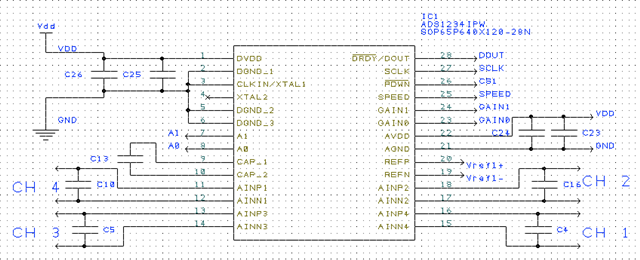
    I've inserted a schematic for the ADC below, all 3 use the same approach.

    What we've called the CS (as in Chip Select) which goes to the power down pin is a separate output for each ADC from our microcontroller, the other control lines are shared between the microcontroller and the 3 ADCs.

    We reset the device every time we go to one of the other 2 ADCs to make a sample. It's not very high speed, so we work through the 4 channels on an ADC, then move on to the next -  more like 1sps on each channel.

    All the control lines go directly to a microcontroller, so all your problem scenarios are possible

    - it could be that we put a control signal high before the Vdd line has stabilised (as that's switched through a transistor by the microcontroller too),

    - the microcontroller pins can supply >10mA

    - before they are configured properly, the control pins could be set as inputs, and I didn't put any external pull up or down resistors on.... 

    It doesn't read well, when you put it like that!

    It sounds like there's a number of ways the software could be causing the problems we've seen, but most likely we've set a control pin high before switching on the supply through that transistor - I'll brief the software developers more clearly to not do that!

    Alex