This thread has been locked.

If you have a related question, please click the "Ask a related question" button in the top right corner. The newly created question will be automatically linked to this question.

TLC3578: Basic Test

Part Number: TLC3578
Other Parts Discussed in Thread: TLC2578

Hi,

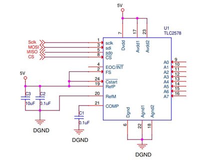
I'm trying to work with TLC3578 through SPI.

The CPU is DSP C674x.

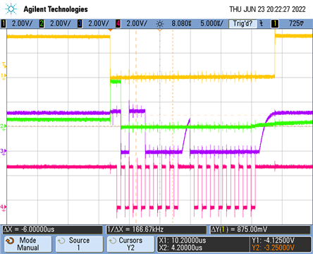
My problem is that the bytes I'm getting back from the ADC don't make much sense to me.

Basically, I repeatedly send commands, each consisting of 2 separate bytes. In pseudo code-

In loop:

{

CS LOW

send 2 bytes (for example 0xb000),  store 2 bytes from rx

small delay

CS HIGH

}


So, for a sanity check, is there a simple transmission I can do for which there's a known answer?


Thank you,

  • Hi Yoni,

    The 0xB000 command you are sending to the TLC3578 should respond with one of the test voltage conditions.  Can you send us a schematic of your setup and a scope capture of your /CS, SCLK, SDI and SDO? 

  • Hi Tom,

    First, let me correct myself, the component is 2578, and not 3578.

    Further details regarding my problem:

    No matter what I send, I get back 0xc003 (I've tried sending 0xb000, 0xc000, 0xd000 and more, with and without writing CFR before the loop).

    Please see below the schematic and scope capture.

    Thank you,

    Rate 1Mhz

    Yellow-/CS

    Purple-SDO

    Green-SDI

  • Hi Yoni,

    The TLC2578 works the same way as the TLC3578.  In the scope trace, it looks like green is SDO and purple is SDI.  If you look closely, you will notice that the green and purple traces are changing state on different clock edges and I suspect the command is not being interpreted correctly.  Try changing the phase of your SPI controller so that data is valid on the falling clock edge.  Also, probe the EOC/INT pin if you can and compare its behavior against Figure 2.

    The hardware default mode of the TLC2578 sets the CFR to 0x800, which puts the device in long sampling mode.  Let me know what happens if  you keep your /CS line low and send another 4 or 5 'dummy' bytes to the part (just write 0x0000).  From there, write (at minimum) 0xAA00 to the part to set the short sampling mode bit.  From there, you should be able to go back to your original 16 bit SPI transfer.

  • Hi, 

    I'm now receiving 0x800 when sending 0xb000, receiving 0x001 (or 0x000) when sending 0xc000,  and 0xfff when sending 0xd000.

    Is this correct?

    As you suggested, I begin by sending 5 dummy bytes (single SPI transaction), then I send 0xAA00 (another transaction), and after that I send read commands.

    I've also changed the clock polarity to fix the state change issue. 

    Below is a capture of sending 0xb000.

    Thank you,

  • Great!  Looks like you are making progress! 

    Those are the correct values for the three conversion test commands. 

  • Thank you very much.