Because of the holidays, TI E2E™ design support forum responses will be delayed from Dec. 25 through Jan. 2. Thank you for your patience.

This thread has been locked.

If you have a related question, please click the "Ask a related question" button in the top right corner. The newly created question will be automatically linked to this question.

ADC121C021: Oddly sensitive to value of capacitor on VIN

Part Number: ADC121C021
Other Parts Discussed in Thread: TLV8541

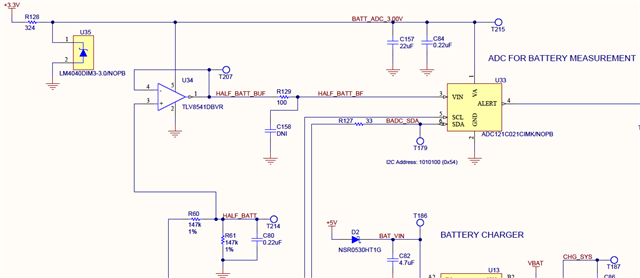
We're using the ADC to measure the voltage of an LFP battery. We divide the battery voltage by 2 and buffer it with an opamp, followed by an optional RC lowpass. The ADC is powered from a 3.0 V shunt reference; schematic is attached at the bottom of this posting. The input signal to the ADC is therefore 0 to 1.825 V.

With the default circuit shown in the schematic, the accuracy of the measurement is fine over most of our range, but at both ends it is not: for VIN below about 0.2 V the ADC reads high by 10% and above 1.5 V it reads low by a few percent.  We tried a few experiments.  Changing the series resistor (R129) to zero ohms had no effect.  Restoring R129 to 100 Ω and trying different capacitor values, we find that 100 pF at C158 fixes the problem. Larger capacitors caused the measured value to bounce around a bit -- maybe the opamp isn't happy with the capacitive load?  A smaller capacitance such as 15 pF didn't give great results either.

We suspect that we're seeing interaction between the sampling capacitor and the outside world.  This is not shocking, but what's surprising is how sensitive it is.

- What would cause the non-linearity we saw below 0.2 and above 1.5 V?

- Why didn't the direct connection of the opamp to VIN improve the performance?

- Is this part unusually sensitive?

- Could any of the register settings impact this?  Turning auto-conversion off vs. on seemed to have some effect, but why would that be?

Thanks,

Scott
  • Hello,

    From the information you shared, it seems that there is a settling issue. The RC circuit after the op amp is actually not optional, it is necessary to make sure the Op amp can drive the ADC input. Connecting the op amp output directly to the ADC will not work properly, as the op amp would then be driving a dynamic capacitive load, which can make an op amp unstable. The resistor separates the capacitor from the op amp output. The capacitor is needed, and should be sized, to drive the sample and hold capacitor internally in the ADC. The rule of thumb is that the external capacitor is 20x the C_SH, which is 30pf for this device. From there, the sample rate of the ADC and GBW of the op amp should be considered to modify the size. This aligns with what you saw when changing the capacitor values, including why auto conversion had an effect, this would have impacted the device sample rate. 

    What sample rate are you using the device at?

    Regards

    Cynthia 

  • Hi Cynthia,

    Thank you for responding.  Here are a few thoughts:

    1. I'll have to experiment to see how much series R is needed to stop the opamp output from seeing the capacitor.  At some point, if that R is high enough, it begs the question as to whether the opamp is worth having vs. just the voltage divider from the battery with a large cap to stabilize it.

    2. We are currently using a conversion time of Tconvert *32, but since we don't need speed nor do we take this reading often, we can use almost any setting.  In fact, to save energy, wouldn't we be better off turn off auto-conversion mode and just have the I2C read trigger the reading? Or does that come with its own set of challenges, such as having to take multiple readings, say, because the first one isn't accurate or something?

    3. How does the GBW of the opamp figure into this once there's sufficient R and C, assuming that the opamp isn't absurdly slow?  This is related to my first point above.

    4. If you were designing this, how would you have approached it?  Did we make this overly complicated given that we're just reading a DC level at an infrequent interval?

    Thanks,
    Scott

  • Scott, 

    Monitoring a battery is a common application for the ADS7142, which is not a direct replacement for the ADC121C021, but has same functionality and more features. One of those features is a window comparator and an Alert pin, that may be beneficial to your application.

    Your methodology is just fine to measure a battery. The voltage divider will follow the battery voltage yet divide it down to be within the ADC voltage range. The op amp then drives the signal to the ADC input, this is helpful when sampling at a faster rate. The GBW helps determine if an op amp can support the sampling rate of the ADC, as a SAR ADC has a switch capacitive circuit. The ADC input needs to settle within the acquisition time, this time is usually very short and thus an op amp is needed.

    With a sampling rate of 27ksps, this means that a conversion cycle is 37us. the conversion phase (hold time) of this is 1us, which means that there is 36us of acquisition time (track time). 

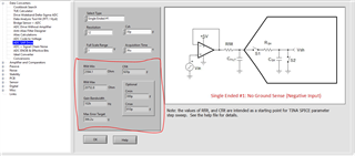
    Using the Analog engineers calculator, the RC values can be solved for, using information from the ADC datasheet. 

    From the below image, with the ADC data entered on the top half, the bottom half displays that the R should be between 2.5k ohm to 20k ohms, when using a capacitor of 620pF.  It also displays the GBW needed from the driving op amp, in this case, 102Khz, which the TLV8541 meets.

    I believe if you use a value for the RC from the calculator, you should see expected performance. 

    For more information on ADCs, there is a whole set of video lectures called: Precision Labs

    Regards

    Cynthia

  • Hi Cynthia,

    Thank you for the update and the info about the tool and videos. 

    We're thinking that we're going to turn off auto-conversion mode, and take readings infrequently from the ADC's point of view, i.e. on a timescale of seconds.  Therefore, the Analog Engineer's Calculator gives absurdly large values for Rfilt. Am I also correct in thinking that a long timescale opens up the option of not using an opamp?

    The datasheet is a little unclear to us, though, about what happens in non-Automatic mode. The text says "In the Normal (non-Automatic) Conversion mode, a new conversion is started after the previous conversion result is read." So does the converter run at maximum speed, or does only perform one conversion after an I2C read, and then it sits and waits for that conversion to be read?  We are wanting the minimum-power setting for when running on battery, but we're not sure what that is.

    I think for the boards we already have built, I'd want to install a capacitor with a value of 620 pF and then experiment to find the minimum value of R which keeps the opamp happy.

    Thanks again,

    Scott

  • Scott,

    Yes, the tool is being updated every so often, and this is a known limit, this is a result of the math being applied without application based scenarios. 

    If the time scale is now in the seconds, then there is no need to scale up the RC values as the calculator shows, the circuit will be able to support any sample rate slower than calculated to use. 

    Yes, with enough time between samples, the op amp can be eliminated. There is a section in the calculator, "ADC Drive without Amplifier" section, that can help to solve for resistor and capacitor values. Note that in this case, the circuit will be simplified to the resistor divider equivalent and a parallel capacitor. 

    This device was released a while ago, and agree the datasheet could be improved. The device is in track (acquisition mode) when a conversion is started, this means the device is essentially idle and not consuming much power. Once a read command is sent is when the conversion is actually taking place. During this time is when the bulk of the power consumption is taking place

    Regards

    Cynthia

  • Hi Cynthia,

    Thank you!  Just one follow-up: in Normal mode, when the ADC is idle, is there a reading buffered and waiting for an I2C Read?  That's what the datasheet implies.  In other words, when we do an I2C Read, are we getting the result of a conversion that is then immediately triggered, or does the completion of the Read trigger a conversion which then sits and waits to be read later?

    Regards,

    Scott

  • Hello Scott, 

    I read thoroughly through the datasheet, as I found it odd that this was not explained somewhere, and I found the information we were missing

    Here it states that the ADC is in fact not in acquisition (track) mode when idle, this is usually the case in newer device, but not here. It also confirms that conversion occurs conversion result is read. The acquisition time then here is fixed to 0.4us. This then can be used to asses the values needed for the RC and the need of the op amp. 

    With the current op amp, the RC values suggested are 10kOhm and 1 uF. What is happening here is that the circuit is now relaying solely on the capacitor to recharge the ADC sample and hold circuit, instead of the op amp bandwidth. Due to this though, the external RC circuit needs ample time to recharge the capacitor, in this case it is 10ms (actually less, but rounded up). this means a new conversion cannot be correctly completed until 10ms, the sample rate is limited to 100hz in this case. 

    The other option is to not use the op amp. As explained before, the external capacitor is now charging the ADC internal sample and hold, thus the same sizing and timing limitation apply. Without the op amp though, the voltage divider, the parallel equivalent,  would need to provide the 10kohm resistance. 

    I hope this provides a clearer resolution 

    Cynthia

  • Hello Cynthia,

    So the sequence sounds like this: ACK fall on SDA, then 0.4 us conversion, then result register gets loaded and that same data is read out on SDA?

    FYI, I tried 10 k series and 1000 pF shunt and the results are not stable.  Maybe this particular opamp is really fussy?  I did try no opamp and just a 220 nF cap, and the results were stable.

    Thanks,
    Scott

  • Correct, that is the sequence 

    That is interesting, it may have been that the capacitor was not big enough and the op amp could not make up the difference.  

    I can see those values operating correctly, with the voltage divider and a 220nF cap, the capacitor will only need 1.789ms to recharge. 

    Regards

    Cynthia

  • But the readings are stable (small sample size, room temp.) with the opamp, 100 ohms and 100 pF, so go figure!

    Scott

  • Scott, well the tool is meant to help guide, I am glad the system is working as desired

    Regards, Cynthia