This thread has been locked.
If you have a related question, please click the "Ask a related question" button in the top right corner. The newly created question will be automatically linked to this question.
Hi,
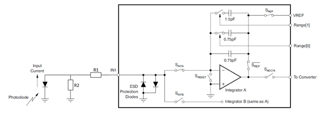
is it possible to reduce a given photodiode current at the DDC316 input in order to aviod a saturated signal?
(The integratoin time is already at 11µs and the capacitor setting is 12pC)
We´ve already tried serveral voltage/current divider configurations but this does not seem to work correctly and leads to significant offset shift effects (especially with longer integration times).
Thanks in advance.
Oliver
Hi Oliver,
Well, looks like you tried what I was going to propose, a resistor divider. Can you show one that you tried and maybe we can look at the issues?
Regards,
Edu
Hi Eduardo,
thanks for your fast reply.
We tried it with a simple resistor divider as shown below.
We made the assumtion that we have (under ideal conditions) a virtual ground at Integrator A(-) during the integration phase - I hope that is correct.
In order to minimize the voltage drop we started with low resistor values (R1 = 10 ohms)
With R2 = 10 ohms we got no signal at all from the DDC.
With R2 = 1k ohms we reduced the DDC-signal to 50%, but with a significant offset drop
Higher values result in an offset drop, so the DDC-signal is below zero (with the photodiode in dark).
Yeah, the resistor divider topology is correct but the values need some adjusting...
The assumption of virtual ground and the input of the DDC is theoretically true but not in the practice. Every DDC has a input voltage vs input current characteristic which depends also of the input gain (feedback cap). See for instance figure 15 of 264 datasheet. I don't have data for 316 so you would have to measure it (apply a current, say with a voltage source + resistor in series with the input pin, and measure the voltage at that pin). From there you can compute the zin in that given setting. I expect something in the kOhm range.
The other aspect is that the value of those resistors is too small...
Can you tell me the range you are trying to achieve?
Regards,
Eduardo
Thank you for the hint with the additional information in the DDC264 datasheet.
With these information in mind, the resitor divider with values in the 220...470kOhm range works fine :)
Great to know!! Thank you for closing the loop with us! I'll go ahead and close the case
Best regards,
Eduardo