This thread has been locked.

If you have a related question, please click the "Ask a related question" button in the top right corner. The newly created question will be automatically linked to this question.

ADS1248: AIN measurement using internal reference for ADS1248

Part Number: ADS1248

Please advise me on how to make the correct measurement, as the measurement results using the internal voltages show different results than expected.

I have created a configuration to measure the differential voltages of AIN5 and AIN6.

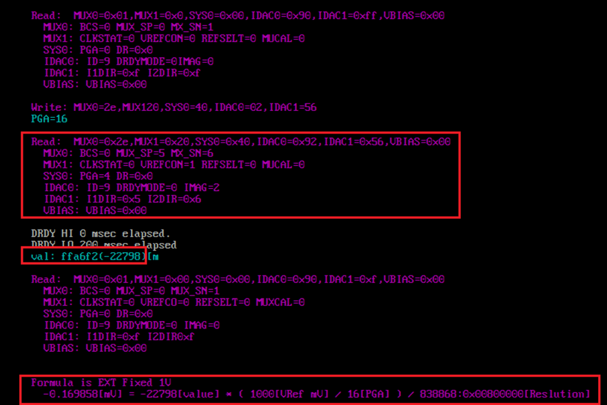
In the external reference measurement, which has already been verified to be correct, the ADC readout for the differential measurement of AIN5 and AIN6 is 0xffa724 (-22748).

The following voltage conversion equation is used

Vout _ext= -22748[value] * ( ( ( 100[IMAG uA] * 2 * 0.001) * 5000[VRef mV] / 16[PGA] ) / 8388608:0x00800000[Resolution] =-0.169485[mV]

or Vout_ext = -22748[value] * ( 1000[VRef mV] / 16[PGA] ) / 8388608:0x00800000[Resolution] = -0.169485[mV]

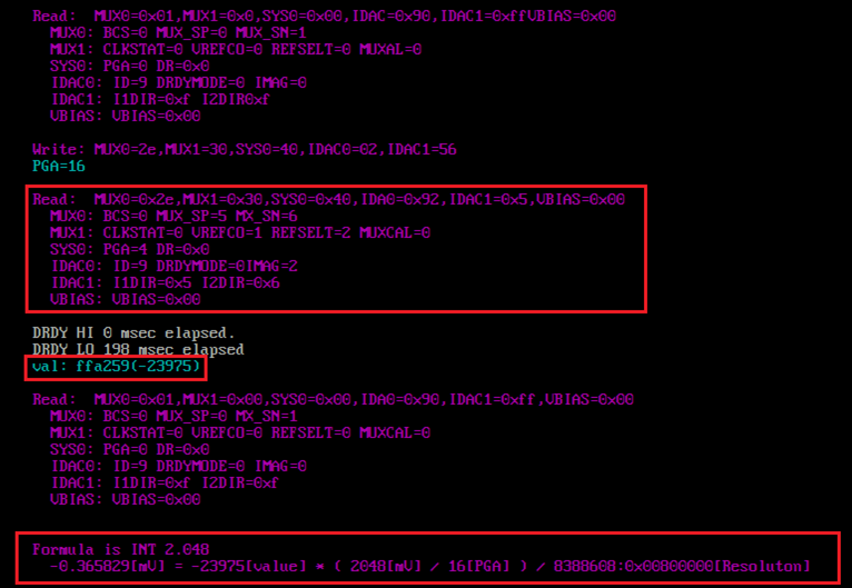
On the other hand, the ADC readout value for the differential measurement of AIN5 and AIN6 using the internal reference was 0xffa259 (-23975). This is almost the same as the ADC readout of the external reference value.

The following voltage conversion equation was used
Vout_int=-0.365829[mV] = -23975[value] * ( 2048[VRef mV] / 16[PGA] ) / 8388608:0x00800000[Resolution])

I think this is a strange result, since the weights per LSB are 2.048 times different, so the ADC readout should be 2.048 times different.

Furthermore, after conversion to voltage, the values should be almost the same.

Can you please tell me why this is the case?

I am not sure what the cause is, but it seems that the internal reference mode is not enabled.

Is it because we are using the wrong register settings or system configuration?

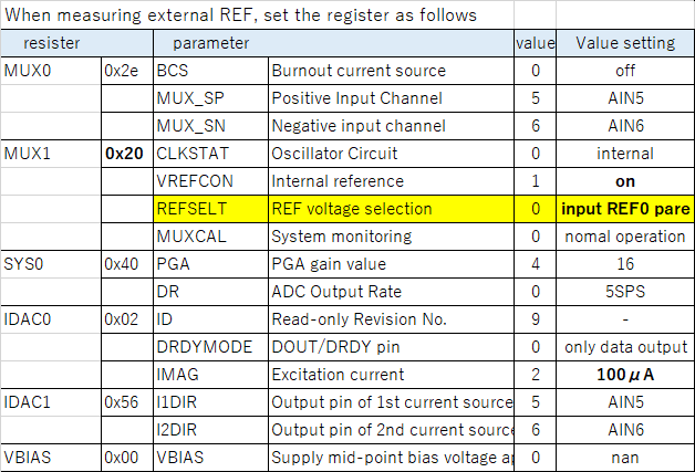
Here are the settings when measuring using the external REF

Translated with www.DeepL.com/Translator (free version)

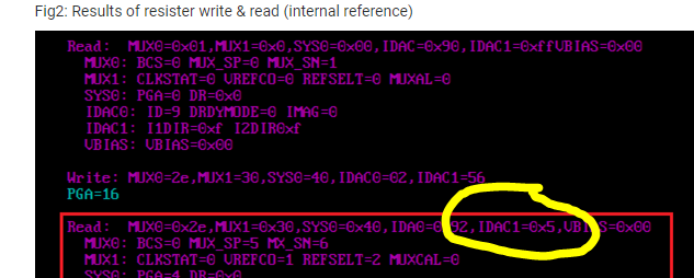
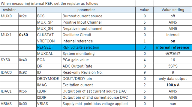
The settings for measurement using the internal REF are as follows

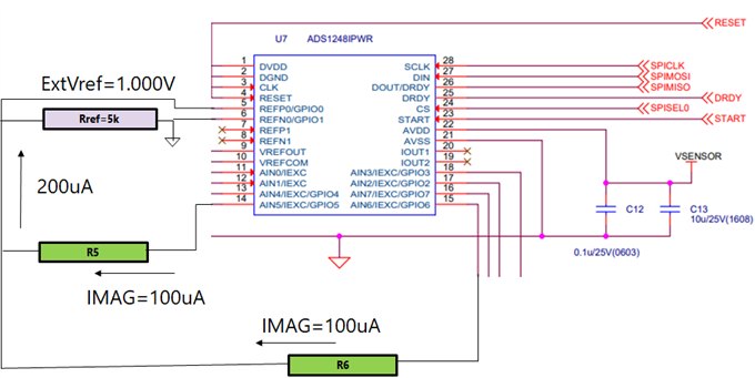
The system configuration of  ADS1248 and measuring resistors is shown in the figure below.

  • Hi Yoshihiko Kurui,

    It seems like you are performing the math correctly in your analysis. The only issue I could see is that the IDAC value is likely not exactly 100uA, so the voltage across the 5k RREF resistor is likely not exactly 1V. Have you measured the voltage across this resistor using a precision DMM (6- or 8-digit)? However, this should not change the calculation a lot.

    Also, what are you measuring? The values you have shown are very small (170uV). Have you tried measuring a known value from a precision source? It might be useful to input a 500 mV signal into the ADC using both reference sources (external and internal). This will help determine if the register settings are being loaded correctly, that the correct channel is being measured, etc.

    On that note, have you confirmed that you are writing to the registers correctly? Please perform a register read back whenever you change the ADC register settings to ensure that the new register settings are being properly loaded into the ADC.

    Let me know what you do to troubleshoot the system and what the results of these tests are

    -Bryan

  • >The only issue I could see is that the IDAC value is likely not exactly 100uA, so the >voltage across the 5k RREF resistor is likely not exactly 1V. Have you measured the >voltage across this resistor using a precision DMM (6- or 8-digit)? However, this >should not change the calculation a lot.

    Using a DMM, measure the voltages on AIN5 and AIN6 respectively.
    But does the difference between the external REF and the internal REF change the IDAC value?
    In this case, it has to change by a factor of 2.048 to explain the voltage values obtained.


    >Also, what are you measuring? The values you have shown are very small (170uV).

    It is reasonable to give a small value since you measured the differential voltage across lead resistors with the same value, AIN5 and AIN6.
    The resistor values used for the measurements are R5=1kΩ±1% and R6=1kΩ±1% respectively.
    As shown in the following calculation, the differential resistance value is a few ohms, so the smaller value is output and is the correct result.
    Expected measurement voltage = (R5-R6)*100uA ~1.7Ω*100uA ~170uV
    (*note) The expected voltage values obtained from external and internal REFs are ideally the same, right?

    >Have you tried measuring a known value from a precision source? It might be >useful to input a 500 mV signal into the ADC using both reference sources
    >(external and internal). This will help determine if the register settings are being >loaded correctly, that the correct channel is being measured, etc.

    If the differential output is small, it will be difficult to determine, so change R5=10kΩ and R6=5kΩ, and re-measure under the condition that the expected measured value is 500mV.
    Expected measurement voltage = (R5-R6)*100uA ~5kΩ*100uA ~500mV

    >have you confirmed that you are writing to the registers correctly? Please perform a register read back whenever you change the ADC register settings to ensure that the new register settings are being Please perform >a register read back whenever you change the ADC register settings to ensure that the new register settings are being properly loaded into the ADC.

    We have already confirmed that both the external and internal REFs are set correctly by reading back the registers after writing to them.
    Please check the following image.

    Translated with www.DeepL.com/Translator (free version)

    Fig1: Results of resister write & read (external reference) 

    Fig2: Results of resister write & read (internal reference) 

  • Hi Yoshihiko Kurui,

    The register read back appears to be working correctly in most cases.

    I am not sure if this is an issue, but the text on the screen for the internal reference read back shows that IDAC1 = 0x5, while it should be IDAC1 = 0x56.

    Is this readback valid? It might be useful to double check the ADC output with a logic analyzer during the read back, just to confirm that the values are correct.

    -Bryan

  • To Dr. Bryan

    To verify that the AIN current values you requested are correct
    I measured the voltage values between AIN5 and REFP0, and between AIN6 and REFP0 with a digital multimeter.

    The measurements were as follows. The voltage measurements were not caught by the tester, so an oscilloscope was used.

    Measured the voltage on AIN5-REFP0
    Measured the voltage at AIN6-REFP0.

    A 1kΩ was inserted between the terminals and 100uA was applied.

    A value of just under 100[mV] was measured for both the internal and external REF settings.

    The result was consistent with the expected voltage value: I*R=100uA×1kΩ=100mV

  • >I am not sure if this is an issue, but the text on the screen for the internal reference read back shows that IDAC1 = 0x5, while it should be IDAC1 = 0x56.

    I will check and answer later.

  • >I am not sure if this is an issue, but the text on the screen for the internal reference read back shows that IDAC1 = 0x5, while it should be IDAC1 = 0x56.

    It just so happens that the data reading data is missing. After repeated checks, the correct values were displayed.

  • Hi Yoshihiko Kurui,

    At this point, it is confirmed that the registers are being written correctly in both cases (external versus internal VREF).

    You have also confirmed using a DMM that there is ~100mV across R5 and R6 and ~1V across RREF when both IDACs are enabled. Can you please confirm that this statement is true when you are using both the external and internal VREF?

    If all of these statements are true, the next thing to review would be the digital communication. Using a logic analyzer, can you post screenshots of the register write and register read, as well as how you are retrieving data from the ADC? If you are using a Saleae logic analyzer, you can just send me the .sal file.

    Also, can you send me the full schematic of your input, including the different resistor values? The image you included in your first post does not show the actual input structure on the schematic, there are just blocks for each component.

    -Bryan