Hi,
In the datasheet, the DAC data register description DAC70501: DATA;13:0],0,0
Does this means needs to add two '0' at LSB before the actual 14 bit data ?.
Regards,
Harris
This thread has been locked.
If you have a related question, please click the "Ask a related question" button in the top right corner. The newly created question will be automatically linked to this question.
Hi,
In the datasheet, the DAC data register description DAC70501: DATA;13:0],0,0
Does this means needs to add two '0' at LSB before the actual 14 bit data ?.
Regards,
Harris
Hi,
Register size is 16bits, and DAC_DATA is 14bits. Basically data format is MSB left aligned.
For example full scale, 14bits is FFFC
Your understanding is correct
Regards,
AK
Thanks for the clarification. However i have one more question that is can we change the dac value simply sending the DAC VALUE command or requires to set another register first (use default setting) ?. Thank you.
Hi,
Can you explain little bit more? I didn't get this question.
It depends on power supply, whether you are using internal or external reference etc.
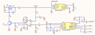
Can you share your schematics?
regards,
AK
My circuit using internal reference (but can be configured to use with external reference as well).

If i want to change the dac output, can it be done by simply sending a single command e.g. 1000 0111 1111 1111 1100 ? or we need to set other registers before changing the dac output value ?.
Hi Harris,
By default, the device is configured for asynchronous updates. That means that all you need to do is send 24-bit SPI command (register address + Data) to register 0x08. The DAC will update directly.
THanks,
Paul
Hi Paul .. thanks for the information. However i have one last question is that does the dac spi interface still be able to function properly if i spi signal amplitude is 3.3V (the dac VDD is 5V). ?
Yes, as long as the logic high voltage is greater than the device's specific VIH voltage level.
Thanks,
Paul