This thread has been locked.

If you have a related question, please click the "Ask a related question" button in the top right corner. The newly created question will be automatically linked to this question.

ADS1256: How to properly configure an ADC to sample dual sum output instrumentation amplifiers.

Part Number: ADS1256
Other Parts Discussed in Thread: INA821, LM27762, , ADS1285, ADS1260

Hello experts, I tried to use the LM27762 to convert the +5V power supply into a dual power supply +-5V for the INA821. Figure 1
According to Figure 2, I will eventually output a +-4V signal, so how should I design the ADC sampling circuit?

This is just a demonstration diagram a bit casual, so there INA821 isn't power decoupling capacitors. 

Figure 1

-------------------------------------------------------------
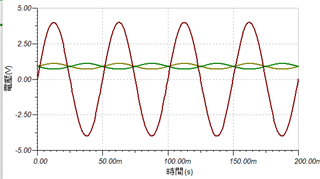
Figure 2

-------------------------------------------------------------

I have an ADS1256 by my side.
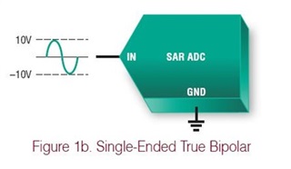
Is this a single-ended bipolar? Or pseudo differential?
And do I need to isolate the GND? I don't understand sorry.
-------------------------------------------------------------
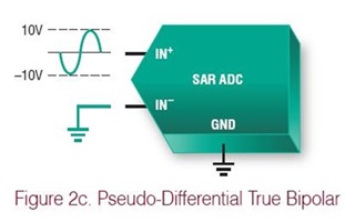
-------------------------------------------------------------

  • Hi LEO_0916,

    The ADS1256 has a true differential input. In fact, most delta-sigma ADCs have a true differential input. The input range definitions you show in your post are more applicable to SAR ADCs.

    Please note that the ADS1256 can only measure a signal up to the supply range, which is basically 0-5V (this range is reduced when the ADS1256 internal buffer is enabled). Therefore a +/-4V signal would have to be level-shifted and attenuated before being applied to the ADS1256 inputs.

    When you say your signal will be +/-4V, are you trying to measure a sinewave with the ADS1256? The ADS1256 might not be the best choice for AC signals due to the way that delta-sigma ADCs sample an input. This might be better suited for a SAR ADC, unless you are measuring a very low frequency sinewave (<1 kHz). If you can provide more information about what you are trying to measure we can make better recommendations.

    Also, you might want to review the SAR vs delta-sigma information in our Precision Labs training material (section 3): https://training.ti.com/ti-precision-labs-adcs

    -Bryan

  • Hello~ I mainly measure the seismic signal between 0.075-20HZ. I will use a differential accelerometer for measurement (The differential voltage is +-0.4V at +-1G). Because I want to improve CMRR, I set G=10 for INA821. This results in the output being at +-4V. If I want to keep things simple, is having the output between 0-5V the bestoption? But then I have to sacrifice higher CMRR. Or use ADC up to 0-10V

  • Hi LEO_0916

    We have high resolution ADCs specifically for seismic measurements. Please check out the ADS128x devices: https://www.ti.com/data-converters/adc-circuit/precision-adcs/products.html#p84=24;32&p1028=1;2&p1130=25;15246

    These ADCs are designed for small-signal, low-frequency seismic measurements. We are about to release a new device, the ADS1285, that includes a gain stage so you would not need the INA821. However, some of the other ADS128x devices also have gain stages, if you need something now.

    Let me know if these devices look interesting to you. Or, if you want to continue using the ADS1256, let me know.

    What is the common-mode signal of the sensor output? You said that it is a differential +/-0.4V, but what voltage is this signal referenced to?

    -Bryan

  • Hello, thank you for your reply~ I will check the new adc you mentioned, my common mode voltage is 0.9v,
    my sensor has two signal outputs, the positive outputs 0.9+0.2V at +1G, the other It is the reverse output that outputs 0.9-0.2V at +1G
    The whole system is referenced to 1.8V
  • Hi LEO_0916,

    One challenge with gaining up the signal to +/-4V is that you will then have to attenuate this signal because most precision ADCs can only accept an input signal up to the supply voltage. And there is no benefit to gaining up a signal that then needs to be attenuated, this is just adding noise to your system.

    I would consider something like the ADS128x or the ADS1260 using a bipolar supply.

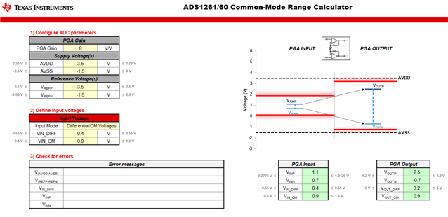
    Below I show an example of how to setup your system using the ADS1260 common-mode range calculator (https://www.ti.com/lit/zip/SBAC200). You can use the LM27762 to generate asymmetric supplies of +3.5V and -1.5V, as shown. This puts the common-mode of your sensor (0.9V) almost in the middle of the ADC input range. The ADS1260 has an integrated, very low noise PGA that can set to a gain of 8 assuming the differential input signal is 0.4V and using a 5V reference voltage.

    Let me know if this makes sense

    -Bryan