This thread has been locked.

If you have a related question, please click the "Ask a related question" button in the top right corner. The newly created question will be automatically linked to this question.

ADS7138: Analog input leakage, AVDD > DVDD?

Part Number: ADS7138

Hello.

I'm going to use ADS7138, and I have 2 questions about it, just to be clear.

(1) Is it ok if DVDD = 3.3V and AVDD = 4.096V? That is, can AVDD be greater than DVDD?

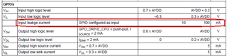
(2) Please check picture below, its from page 8/90 of datasheet. I will use all 8 inputs as analog inputs. The question is, when the pin is used as analog input, the maximum input leakage is also 100nA?

Regards,

Jeferson.

  • Hi.

    Here is my current schematic.

    The informations of resolutions shown are not corrected.

    PCB-SX-L_06_sch_01.pdf

    Regards.

  • Hello Jeferson,

    1. The AVDD and DVDD supplies can be set to any value within the ranges specified in the recommended operating conditions table. AVDD > DVDD is a valid use case.
    2. The analog input leakage current is primarily because of the ESD protection diodes at the analog inputs. The 100nA leakage will be applicable for analog input configuration as well.

    Regards,

    Rahul

  • Hi Jeferson,

    I have reviewed the schematic for ADC connections. The power supply decoupling looks ok. The schematic does not include the pull-up resistors for the I2C signals, I presume these pull-up resistors are elsewhere in your schematic.

    It is recommended to use a charge-kickback filter capacitor at the analog inputs. You can refer to the recommended schematic (figure 30) in the EVM schematic. You can use the Analog Engineer's Calculator to calculate the suitable RC values.

    Regards,

    Rahul

  • Hi Rahul.

    Thanks very much.

    The I2C pull-ups are in another schematic page.

    What happens if I don't use these capacitor at the analog inputs? Because my board is so much space-constrained, probably I won't have enough space.

  • Hi Jeferson,

    The maximum sampling rate of the ADC will need to be limited to around 450kHz.

    The external signal source, resistive voltage divider in your schematic, needs to drive the sampling capacitor (12pF) of the ADC. The external impedance (R) and the ADC's sampling capacitor (C) will form a RC circuit with time-constant (τ). To achieve 12-bit precision, ln(212) i.e. 8.3 time-constants are required. If the external impedance is 7.5kΩ, 1τ = 7.5kΩ x 12pF = 90ns. Hence total settling time required for 12-bit accuracy will be 90 x 8.3 = 749ns.

    The conversion time of the ADC is 1400ns in standard I2C mode. The maximum achievable speed will be conversion time + acquisition time  i.e. 1400ns + 749ns = 2149ns i.e. 465kHz.

    Regards,

    Rahul

  • Rahul,

    Thanks very much for you explanation.

    Actually I forgot to explain better about the use of ADS7138 for this design, we are not using it aiming a high sampling rate, but because it is a part number that is still well available in the market, mainly due to this, and due its features.

    We only need for each individual analog input a 1K samples/second, that is enough. Maybe at maximum 5K samples/second (considering each individual input), but 1K samples/second on each individual input should be very fine.

    So I think there will be no problem if I don't place the capacitors at the analog inputs, right?

    Regards,

    Jeferson.

  • Hi Jefferson,

    At 1ksps/channel, it will be ok to not use the charge-kickback capacitor for 7.5kohm source impedance.

    Regards,

    Rahul

  • Ok, thanks.

    But for the 7 current inputs there are 100R shunt resistors to GND, and between them to the analog inputs there are 22K limiting resistors, which is greater than 7.5K, but should be not problem also.

    Regards. 

  • Hi Jeferson,

    The 22kΩ impedance is ~3x higher and hence the minimum settling time for 12-bit settling will increase to 2.25μs. The maximum sampling rate will be 1400ns (conversion time) + 2250ns (settling time) i.e. 275kSPS.

    Regards,

    Rahul

  • Hi Rahul, thanks very much.

    When you calculated above the maximum sampling rate as 275kSPS, does this mean 275kSPS on each channel? Or if reading 8 analog channels, 275/8 = 34.3kSPS per channel? SO, if reading the 8 analog channels, it would be, at maximum, 275kSPS or 34.3kSPS per channel?

    Regards,

    Jeferson.

  • Hi Jeferson,

    I calculated the ADC core speed as 275kSPS. This speed will get divided across the number of analog input channels selected. If all 8 channels are sequenced, the speed per channel will be 275kSPS/8.

    Regards,

    Rahul