This thread has been locked.

If you have a related question, please click the "Ask a related question" button in the top right corner. The newly created question will be automatically linked to this question.

ADS1232: False readings

Part Number: ADS1232

Hi,

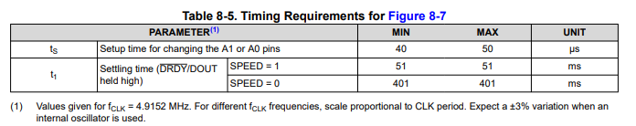
we observe a weird behaviour.
We switch the ADC settings at every conversion:
state 1: GAIN = 128, channel 1
state 2: GAIN = 1, channel 2
the speed is always high (80 Hz).

If everything is OK, in this test channel 1 (connected to a load cell) reads about 527000; channel 2 reads about 234000 (a potentiometer)

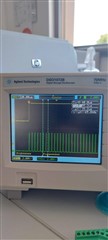
Sometimes we get an out-of-scale reading (for example all 0's or all 1's or also too many 1's :)); see the following oscilloscope tracks (DOUT is yellow, SCLK is green). There is always only one spike at a time (they don't go in clusters) and that happens about 10 times per hour. It happens on both channels.

The problem is there also if we don't change settings (they stay the same all the time and we read only channel1).

Sometimes it also looks like the ADC starts sending data before the clock starts:

We realized that there was a problem: sometimes we started reading the ADC with a delay after DOUT went low:

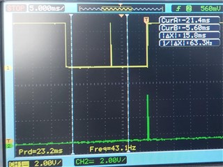
and it looks like the ADC has a spike, even if not clocked.

Better reading the datasheet we found out that the data must be read within t7 = 12.5ms (figure 8-9), and we didn't find a different value for t7 if you read more than one channel, even if in this case the conversion time raises to 50 ms.

So we modified the firmware to read the data within 12.5ms.

After this modification, the problem is fixed if we don't change settings, but if we change settings at each conversion it is still there, even if with much reduced frequency.

Do you have any knowledge or suggestion about this problem?

Kind regards,

  • Hi Matteo,

    It is difficult for me to tell when you decide to read the conversion data.  The best method to use is an interrupt driven system where DRDY/DOUT is not only connected to the SPI bus, but is also connected to a GPIO so that it can be monitored for a high to low transition and trigger an interrupt.  As the pin is dual function this can be somewhat confusing as at any time the conversion completes there will be a high to low transition.  If the conversion update takes place during the read conversion cycle the data will be corrupted.

    Where there are issues is when using a timer method or polling for the DRDY/DOUT transition.  When using the timer method (read every 12.5ms) this can become a problem as the internal oscillator of the ADS1232 can vary as much as +/-3%.  The variation directly relates to conversion period which can also vary by +/-3%.  When using the polling method, you need to make sure that there is enough time to capture the transition from high to low.  This is easiest is if the last bit of the previous conversion is a high, or if an extra SCLK clock is sent in the communication to force the bit high. 

    One advantage of switching channels is the conversion is restarted and DRDY/DOUT is forced high.  As the digital filter is sinc4, the data are not valid until the 4th conversion completes (12.5ms * 4 = 50ms).  You need to add some additional time for the filter to reset and the conversion to restart as given in the following table:

    Note that the times can vary somewhat if the internal oscillator is used by as much as +/-3%.

    So the key here is to properly monitor what is happening on DRDY/DOUT to start the read of conversion data results as soon as possible following the high to low transition on DRDY/DOUT.  As you have already noted, the conversion must be completely read from the ADS1232 before the next conversion results are posted.  As you can see, using an interrupt method is best to ensure that the results are consistent and read in a uniform fashion.

    Best regards,

    Bob B