This thread has been locked.

If you have a related question, please click the "Ask a related question" button in the top right corner. The newly created question will be automatically linked to this question.

ADC12D1620QML-SP: TSW12D1620 Evaluation module

Part Number: ADC12D1620QML-SP

Hello,

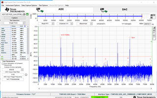
I am evaluating two TSW12D1620 eval boards. I am a seeing a fixed -50dBm spur at 400MHz on both cards with or with a the 1.6GHz clock inputted which make me feel it is something I have wrong in my setup. I am following the evaluation guide and the only deviations from the instructions I had were on step 2.13 where it mentions specific files to select. I found files in the folders that had similar wording but slightly different and I am not sure if those are the issues. Because of the fixed spur I see at 400MHz what happens is I see my 147.77MHz carrier beats with the spur so in my spectrum I see the carrier and a bunch of products of the spur +/- N carrier. I am using an external clock in all cases.

Where can I find the following files just to ensure I am following all the instructions exactly how the guide describes?
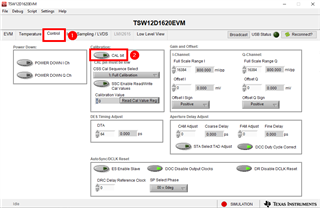
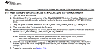
Step 2.13

TSW14DL3200_FIRMWARE_COMPONENT_MODE_800M.bin (I only found a file call "TSW14DL3200_FIRMWARE_COMPONENT_MODE" in the folder

ADC12D1620_NonLSPSM_Demux_nonDES_DCLK90_DDR    (I could not find this specific file but a version of that typ of file that does not mention the DCLK90 in the name)

Thanks,

Mickel

  • Hi Mickel,

    Can you please send the screen shot of the spectrum showing the spur. 

    Have you tried running the calibration when you see the spur? 

    If not here is how to do calibration.

    1. Goto control tab on the gui.

    2. Click the cal bit from 0 to 1  to trigger calibration. 

    Regards,

    Neeraj

  • Hello,

    Can you please provide me with the following files just so I can rule out that these are not the cause of my issues.

    TSW14DL3200_FIRMWARE_COMPONENT_MODE_800M.bin 

    ADC12D1620_NonLSPSM_Demux_nonDES_DCLK90_DDR

    I have pictures I could send but I am confused how to attached on this forum. 

    Thanks,

    Mickel

  • Hi Mickel,

    I have attached requested files. 

    https://e2e.ti.com/cfs-file/__key/communityserver-discussions-components-files/73/TSW14DL3200_5F00_FIRMWARE_5F00_COMPONENT_5F00_MODE_5F00_800M.BIN

    https://e2e.ti.com/cfs-file/__key/communityserver-discussions-components-files/73/ADC12D1620_5F00_NonLSPSM_5F00_Demux_5F00_DES_5F00_DCLK90_5F00_DDR.ini

    To attach the files please click the insert and then click the upload button to load the flies

    Regards,

    Neeraj

  • Hello,

    I attached the photos below. the first figure shows the sampled signal first with no RF applied (you see a 400MHz tone) followed by a 147.77MHz RF signal applied that is at about -30dBm. I shift the RF signal by 10MHz and you will see how the products/spurs in the waveform are tracking one to one in frequency where the high side products are shifting down 10MHz. I have a 11dBm 1.6GHz clock signal into Devclk and I am only driving one of the single ended AIN  (I channel) inputs and all other RF connectors are left open and not terminated with 50ohm loads. I measured the dinput with a spectrum analyzer and saw that there is a 250MHz leakage at -40dBm as well as 500, 750, 1GHz leakages that are about -60dBm or less. Keep in mind this is with no 1.6GHz clock connected so I am assuming this is either noise out of the ADC coming back out of J21. I have two evaluation boards and both exhibit the same issue. Any ideas? 

    I will try the files you sent me and see if that resolves the problem but I can guarantee that the clock signal and RF inputs are clean so this is either some internal leakage issue with the ADC, fpga firmware issue, or something else. Once I add those files I should be 100% identical to the user guide instructions.

  • Please find the attached file. 

    https://e2e.ti.com/cfs-file/__key/communityserver-discussions-components-files/73/ADC12D1620_5F00_NonLSPSM_5F00_Demux_5F00_DES_5F00_DCLK90_5F00_DDR.allow

  • Hello Neeraj. I believe I got it working now. My main issue was I had the ECEn pin pulled high so basically I had no way of controlling the hardware using the EVM GUI and most of the spurs I was seeing were due to incorrect interpretation of the sampled data thinking it was in DES or nonDES, and SDR or DDR etc.

    My last request is can you please send me the file? 

    ADC12D1620_NonLSPSM_Demux_nonDES_DCLK90_DDR.ini

    Also Where can these files be found because I might want to play between different demux,DDR/SDR, and various modes of the device?

    Thanks,

    Mickel.

  • Hi Mickel,

    I sent the file in my previous post. 

    All the other files should be location at following location on your pc. 

    C:\Program Files (x86)\Texas Instruments\High Speed Data Converter Pro\14DL3200 Details\ADC files

    Regards,

    Neeraj

  • You sent the DES version. I want the nonDES version. Also I know where the folder is but in my directory there were only like 3 different types initially. The one you sent me gave me a fourth option but I am not sure if I should have more or not. How many files should exist for the ADC. I am working on a closed system that does not have internet so I am not sure if I do not have an update.

    Thanks,

    Mickel

  • Here you go. 

    https://e2e.ti.com/cfs-file/__key/communityserver-discussions-components-files/73/ADC12D1620_5F00_NonLSPSM_5F00_Demux_5F00_nonDES_5F00_DCLK90_5F00_DDR.allow