This thread has been locked.

If you have a related question, please click the "Ask a related question" button in the top right corner. The newly created question will be automatically linked to this question.

ADS1248: CMRR TESTING

Part Number: ADS1248
Other Parts Discussed in Thread: ADS1262

Hi Joseph Wu,

I do saw your reply on CMRR and NMRR testing: ADS1299 EVM CMRR measurements. - Data converters forum - Data converters - TI E2E support forums

it`s quite clear, but I do have some more question on it:

1, what common mode voltage range should used of CMRR testing when PGA in high gain(for example, G=32), in your post I saw that you short positive&negetive input together, then connect to common mode voltage of:2.4~2.6V for G=32 CMRR tesing, but in the datasheet of ADS1248 I found the common mode input range is:

as we short input, in Vin is zero, thus, the common mode input range is VSS+0.1V to AVDD-0.1V for all gain, so my concern is why we do not use this range for CMRR testing but use a much samller CM range(2.4~2.6V), or what exact range do we use for ADS1248 test(for datasheet spec)?

2, for NMRR or CMRR AC testing, if the data rate is lower than 50/60Hz, then aliasing will happen, and also as internal filter exsit, attenuation will happen, for the data caculation, how to deal with the aliasing  and attenuation?

Thanks very much.

Regards, Zhe

  • Hi chen zhe,

    It is true that the common-mode equation used for the ADS1248 PGA is not limited to the range that Joseph suggested in the other e2e thread. If you have a 0V input, then technically VCM can be anywhere within the range of AVSS+0.1 and AVDD-0.1. However, since you will be measuring real signals and want to understand how the CMRR affects these real signals, you should consider that your actual VCM range will be much smaller in practice.

    I would consider the differential input voltage that the ADS1248 can support. For example, at gain = 32 and VREF = 2.5V, the input range is 2*2.5/32 = +/-156mV. I would then use this range relative to your mid-supply voltage ( [AVDD-AVSS] / 2). If AVDD = 5V, then mid-supply is 2.5V and your range is ~2.35V to 2.65V, which is similar to what Joseph recommended.

    For NMRR testing: you can only get rejection of 50/60Hz signals using data rates that are less than 50 and/or 60 Hz. You can see in Figures 57-60 in the ADS1248 datasheet that the ADC sinc filter has nulls at 50/60 Hz that inherently reject these frequencies. If you sample faster than 50/60 Hz, the ADC sinc filter will not reject these frequencies and the NMRR will not be very good. In fact, Table 10 shows the expected rejection and it is not even specified for data rates >20 SPS.

    -Bryan

  • Hi Bryan,

    Really thanks for your comments, some further questions may need your quick confirm:

    1, CMRR spec at G=32 in datasheet of ADS1248 was not tested in the CM range of  AVSS+0.1 toAVDD-0.1? but in about 2.4~2.6V, Right?

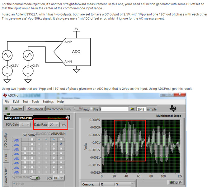
    2, if DR is lower than 50Hz, for example 20Hz, then we will get an aliasing waveform as below:

    then how we calculate the amplitude of ADC measured signal, use FFT? but the 50Hz frequency will be change to another one?

    Thanks.

    Regards, Zhe 

  • Hi chen zhe,

    Another way of thinking about the input signal for the CMRR test is to maximize the absolute input voltage range instead of the VCM range. To maximize the absolute input range, you would set the VCM signal exactly at mid-supply. For example, if AVDD = 5V and AVSS = 0V, then VCM = (5V - 0V)/2 = 2.5V. You can then enter this value in the ADS1248 VCM equation to determine the value of VIN(max) that is equal to 2.5V at whatever gain you choose.

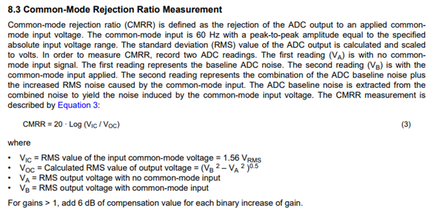
    Using the same settings and G = 1, VIN(max) = 4.8V when VCM = 2.5V. Using G=32, VIN(max) = 150mV. This process is described in the ADS1262 datasheet (shown below), though it can be used for the ADS1248 as well. Joseph was effectively describing the same thing, but in a different way.

    I'm not sure I understand the question about NMRR. Aliasing will occur, but the point is that the digital filter reduces the signal power of 50/60Hz such that the fundamental signal, and its aliases, do not significantly impact the measurement. How significantly the 50/60Hz (and any aliasing) affects the measurement is determined by the NMRR test that Joseph described.

    -Bryan

  • Hi Bryan,

    Got it, thanks.

    Regards, Zhe

  • No problem, chen zhe, glad we could help

    If you have additional questions, please start a new thread and we can support you there.

    -Bryan