This thread has been locked.

If you have a related question, please click the "Ask a related question" button in the top right corner. The newly created question will be automatically linked to this question.

ADS5294: Abnormally high VCM = 1.15V

Part Number: ADS5294

Hi,

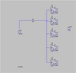
-We are using an ADS5294 VCM output pin 68 to connect to 5x differential opamps LTC6362 VOCM inputs. Each VOCM input of each LTC6362 has a 100 ohm and 0.1uF LPF.LTC6362 are powered by 5V Single ended supply. ADS5294 is powered by 1.801V precisely.

-Differential outputs of the LTC6362 are DC coupled( after antialiasing filter) to the inputs of the ADS5294. ( the common mode voltage inside ADS5294 on AIN+/- pins should not clash with the common mode of LTC6362 as they are  the same voltage( Spice simulation clearly shows that, even the ADS5294EVM board uses  DC coupled )

- The VOCM input impedance of LTC6362 is 170K( simulated in the below spice simulation as 2x 340K ohms as per LTC6362 data sheet)

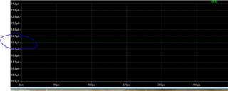
The total current through VCM pin is 24uA in my simulation below, data sheets states 5mA VCM current capability( that is why i did not put a buffer)

-We are using our own board - not ADS5294EVM

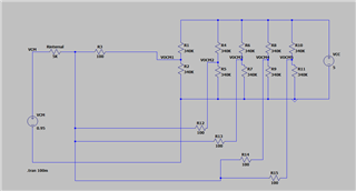
We are reading VCM = 1.15V on each LTC6362VOCM input and on ADS5294 pin68. Spice simulation shows that in order to see VCM=1.15V, the internal resistance of the VCM pin 68 of  ADS5294 must be ~5K. That implies  the VCM is unbuffered, is it?


Question 1:  What is the VCM pin output impedance of ADS5294? Is Vcm Output pin buffered or unbuffered?

Question 2: What could cause VCM to be 1.15V . Do I need soft reset before i measure the pin 68

Thanks,

LT

  • Hi LT,

    Thanks for reaching out.

    The VCM pin has a output buffer which can drive 5 mA of current through the VCM pin. And it should generate 0.95V as stated in the datasheet. 

    Your calculations looks fine to me and hence I suspect that could be that the amplifiers are loading the buffer (meaning current is getting sinked in the buffer).

    Hence the voltage measured is higher.

    To verify if, is it possible for you to remove the output amplifiers connection and measure the VCM voltage?

    If it is 0.95, then this theory that it is sinking current is valid. Else, we'll have to debug why it is happening?

    Thanks & regards,

    Abhishek

  • Hi Abhishek,

    Yes, I do think that the amplifiers are loading the VCM , but they should not. 

    From the following simulation below, you can see i am drawing 20uA( micro amps for all 5 opamps) and the data sheet says 5mA.  20 uA can not load a buffered VCM with 5ma current capability, hence my question.

    Edit: I can see the VCM buffer sinking the current. The right approach would be to put a buffer in between. Does TI offer a sub for LTC6362, that has an high input impedance( not just a voltage divider at the input), is powered by 5V, and VOCM can take 0.95V.

    Most of the TI FDA have 100-200K input impedance on VOCM which wont work in my case. I am trying to fix the issue without re-spinning boards

  • Hi LT,

    Yeah, I agree. Most likely scenario is that the VCM buffer inside is sinking the current and hence its voltage is rising.

    Let me check the same in my lab setup by introducing current in to the pin and measure the current sinking capability of the buffer.

    In terms of alternate, I'm not sure, I'm the right person to suggest an amplifier. I can connect you to the product line supporting FDA. They would be able to recommend you better.

    Kindly allow me some time to check on these two things.

    Regards,

    Abhishek

  • Hi Abhishek,

    Since the application or rather the interaction between ads5294 VCM(0.95V) and an FDA  opamp VOCM ( mid point voltage = 2.5V), is such that there is always a sinking current - from opamp( 2.5V) towards the ads5294(0.95V), we found out that the ADS5294 is very sensitive to sinking current - e.g 30-40uA of sink current throws off the 0.95V bias. Also we found out that the sinking current must be less than about 5uA, so the bias is not affected. That means  the diff opamp vocm pin input resistance must be very high - >1.8Mohm. Most of FDA have 100K-200K input impedance. the safe bet is to use an opamp buffer between VCM and VOCM. the sinking current is still there but external opamps are better at handling uA  sink current that ads5294 VCM pin. It would be a good idea in the data sheet to use the sinking current and not the VCM sourcing current capability as VCM ( for ads5294!)never source current.  We are still testing. Will update that post once we replace the opamps. 

  • Hi Lach,

    Yes, please do share your findings. Meanwhile I will discuss this issue with my team and see if there is anything that could be done to increase sink capability of the VCM buffer.

    Regards,

    Abhishek

  • Hi Abhishek,

    We got the ads5294EVM board as well to compare it to ours. So on power up with no reset( e.g when no command  reg <00> 0x0001 is sent)

    Both the EVM and our board, the VCMs were not 0.95V. it was  around 2VDC.  (Unplug the USB cable on EVM board, recycle power, and measure VCM). We are not sure what the VCM pin defaults to on POR( 0.95V out or 1.5V REF in). Data sheet suggests it defaults to VCM output = 0.95V typical- but it isnt!

    But once we issued a soft reset command, on both the boards, the VCM became 1.00V. Since the spec is 0.95+/- 0.05. We were happy with that.

    So it seems soft reset is setting the registers to default values whereas on power on reset, registers are undefined.

    To make sure we are not fooling ourselves, i lifted up the ads5294 VCM pin off the board. So with no load attached, on POR, the VCM pin was again 2VDC. Once i sent a reset, the pin went to 1.00VDC. So it wans not the load but rather the way the ADC defaults on POR. So sending soft reset is mandatory -power cycle wont do it

  • Hi Lach,

    Glad to hear that you figured out the issue. 

     I will put this observation on our datasheet update list, and will surely put up a note in the datasheet for this.

    Thank you very much.

    Regards,

    Abhishek