This thread has been locked.

If you have a related question, please click the "Ask a related question" button in the top right corner. The newly created question will be automatically linked to this question.

ADS1100: ADS1100 nonlinear spots in output

Part Number: ADS1100

Earlier question regarding nonlinearity of ADS1100 was locked and we could not update results to this thread. Therefore, a new thread was created. 

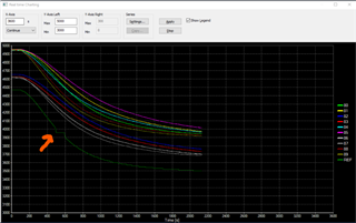
Regarding voltages at IN+ and IN- , a scope image is attached below. 

The resolution of the scope isn't enough to distinguish voltage differences with small resistance value changes, but one should expect it to follow the external circuit resistance changes. 

Below is also some data collected from the I2C circuit using a logic analyzer. First, signal in freezed condition:

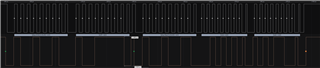
And then in normal condition:


What we can establish from these and earlier results is following: 

- Small input changes in certain ranges will result in same values being sent via I2C by the ADS1100.

- ADS1100 will keep sending the same value - i.e. will not stop sending momentarily. 

- It's difficult to reliably measure IN+ and IN- voltages as the nonlinear range is quite small. However, as these are used for temperature measurements, these have a influence to our measurement output, which will result in errors. 

  • Hello, 

    To make sure I understand correctly, the current situation. At a specific output measurement of the ADC, the device will continue to output erratic measurements that do not correspond to the input voltage. This will continue until the input signal will pass a certain threshold, and then the ADC measurements will revert back to the expected outputs? is this correct?

    In the previous post, you mention that the communication from the device "freezes" which I understand to mean that the data from the device will continue to be the same no matter any changes to the input signal nor device communications. Is this correct? The two images you shared do not show this, thus I am no sure what you mean by "freezing" 

    The second frame in both scope shots you shared have 10 SCK pulses, instead of 9, with some timing measurements shown. I would suggest removing the extra 10 pulse all completely. The timing parameters that need to be checked should be in relation from SCL to SDA. Linked are the timing requirements for I2C ~click here~ page 44. I would suggest to confirm that T_VD_ACK is meeting requirements.

    Regards, Cynthia

  • Hello, 

    thank you for your response. There has been a long gap between earlier measurements and recent ones, but to summarize:

    - The output of the ADC continues to work as flawlessly, until the ranges mentioned in earlier posts occur. The output will behave exactly as seen in the graph below, where temperature is changing constantly as time progresses. The REF output slope is continuous, until a "step" occurs, which can clearly be seen in the graph. The measurements we are doing is supporting this behavior. 


    What we mean by freezing is this - the ADS output value doesn't change but the ADC still keeps sending the same output via I2C even if the temperature is constantly changing. So the temperature can change up to 1 degrees Celsius without it being detectable. 

    Hope this helps. 

  • Thank you for the summary, what is the REF in this case? Is this VDD of the ADS1100?  Has the schematic changed since the last post? 

    About the freezing, you mentioned in the previous post that once the freeze happens, a power cycle does not fix it, is this correct? do you know when the freezing occurs? is it related to the step?

    How many devices are experiencing this?

    Regards

    Cynthia

  • Hello, 

    thank you for your response. 

    REF is purely a temperature output from the device - i.e. REF is not measured directly from the circuit. The previous graph was merely comparing the REF device to other products (not relevant to this case). It was only intended to show how the device output behaves in the problematic region. Device output is based on ADS1100 digital output - without really any relevant filtering added, which could affect the device output.

    After doing more measurements from IN+ and IN- and with a resistance decade box connected instead of a PT1000, following results were noted:

    - Voltage between IN+ and IN- changes inside the problematic range ~0.05 mV with a difference of 1 Ω, i.e. every 1 Ohm change in sensor resistance changes the voltage between IN+ and IN- ~0.05 mV. 

    - Voltage between IN+ and IN- changes outside the problematic range ~0.15 mV with a difference of 1 Ω

    That is, voltage change behaves differently in the range, where digital output of ADS1100 is "frozen". Measured voltage in problem range is around 138 mV. 

    We measured also the voltage difference directly from PT1000 connectors:

    - Voltage between PT1000 connectors changes inside and outside the problematic range ~0.20 mV with a difference of 1 Ω. Behaves as expected.

    What we do see is, that the measuring circuit near IN+ and IN- is very sensitive and all values are average values from the measuring instruments. However, distinctive differences can be noted.

    The problem is repeatable and can be replicated with every device. We can always find the spot where it happens and it's always with the same resistance values / voltage difference. There the ADS1100 digital output is always "frozen" - until we exit the problematic region and it starts behaving normally. Power cycle doesn't affect it. The device is tested with both AC and DC supply voltage - no influence. Circuit design hasn't been changed since early posts.

    As of today, the amount of devices are counted in tens of thousands as same circuit is used in several device types. Currently the measurement range behaving nonlinearly doesn't correspond to typical temperatures measured - i.e. the problem is not evident to the end user. However, we need to understand the problem to know how to avoid it in future designs.

    Regards

  • Hello,

    I am asking my colleagues for ideas on this, the device was released about 2 decades ago, thus hoping they will have some background on this. 

    What PGA setting are you using?

    The total unadjusted error (TUE) of the device, based on PGA setting can range from 2.5mV(PGA=1) to 413.054 uV (PGA=8). Thus, even when using the highest PGA setting the 0.15mV change would be within device performance across temperature. This may just be how the device functions. 

    Regards

    Cynthia

  • Hello, 

    and thank you for your response. 

    We're using default 8 SPS and PGA 8 with single conversion. 

    We've been using ADS1100 for quite some time and this feature was noted by accident. Without knowing more about the internals, we're thinking about ADS having certain specific overlapping ranges where some internal adjustment is needed to respond to the changing input. This could possibly explain what we are seeing.

    Any info from your colleagues is appreciated. 

  • After gathering some background data, it seems you may be on the right path

    The device impedance changes with the gain setting, at PGA set to 8, the differential input impedance is 300Kohm. the input impedance can usually be neglected, unless the input source has a low impedance, in this case the input resistors. Thus the ADS1100’s input impedance may affect the measurement accuracy. This, combined with temperature may be affecting the device measurements. 

    Overall, this may be related to the input settling. One simple way to test this is to short out R3 and R4 in your schematic. If the error goes away or is improved, then this would be indicative. 

    Regards

    Cynthia

  • Hello, 

    and thank you for all the effort. More or less it seems to be an issue with input settling. With some measurement devices we're able to influence the circuit in such manner that the "dead zone" or "step" will go away - meaning there's probably some added capacitance etc. in the circuit. As it is strictly focused on certain digital output values from ADS1100, it's highly probable there's something going on inside the ADS in these areas. We will at some point do some testing and can report also here unless this thread is locked. 

    Regards, 

    Jonas