This thread has been locked.

If you have a related question, please click the "Ask a related question" button in the top right corner. The newly created question will be automatically linked to this question.

ADS1293EVM: Channel 3 Signal is Noisy in 5 Lead ECG

Part Number: ADS1293EVM

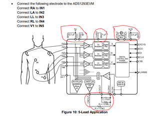
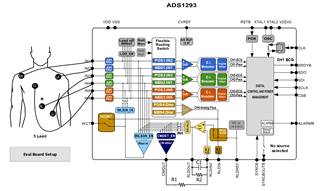
Hi I am using the ADS1293EVM and have connected the inputs to a cardiac simulator. I have made the connections as per the below image

Following are the Register Values that I have set:

0x00,0x00
0x01,0x11
0x02,0x19
0x03,0x35
0x04,0x00
0x05,0x00
0x06,0x00
0x07,0x0f
0x08,0xff
0x09,0x00
0x0a,0x07
0x0b,0x01
0x0c,0x04
0x0d,0x01
0x0e,0x02
0x0f,0x03
0x10,0x05
0x11,0x02
0x12,0x04
0x13,0x07
0x14,0x00
0x15,0x00
0x16,0x00
0x17,0x05
0x18,0x00
0x19,0x00
0x1a,0x00
0x1b,0x00
0x1c,0x00
0x1d,0x00
0x21,0x01
0x22,0x20
0x23,0x20
0x24,0x20
0x25,0x00
0x26,0x00
0x27,0x08
0x28,0x00
0x29,0x00
0x2a,0x00
0x2b,0x00
0x2c,0x00
0x2d,0x00
0x2e,0x33
0x2f,0x70
0x30,0x00
0x31,0x00
0x32,0x00
0x33,0x00
0x34,0x00
0x35,0x00
0x36,0x00
0x37,0x00
0x38,0x00
0x39,0x00
0x3a,0x00
0x3b,0x00
0x3c,0x00
0x3d,0x00
0x3e,0x00
0x3f,0x00
0x40,0xff
0x50,0x00
0x60,0x00
0x62,0x00

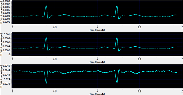
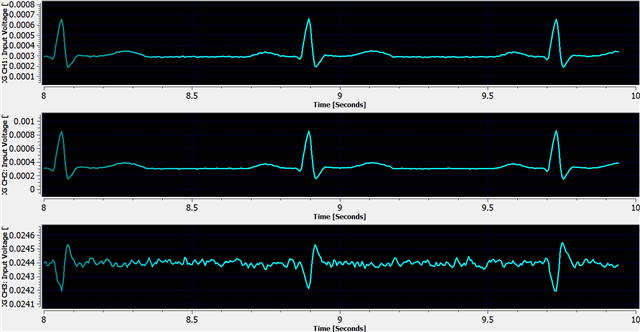
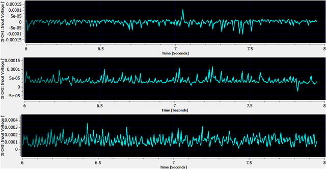
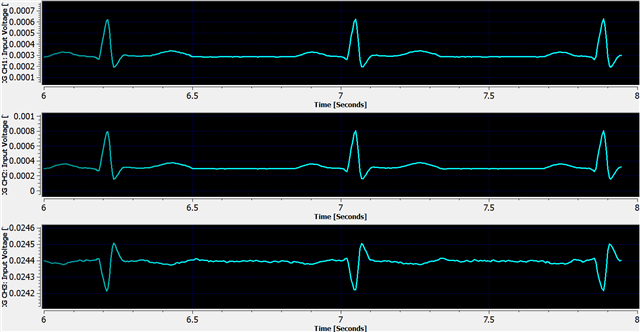
I have set all the INA to High Resolution Mode. SDM are at 102400 Hz. R1 Rate set to Standard, R2 rate set to 4 and R3 rate for all channels are at 32. Now I am getting the below graph:

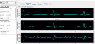
While Channel 1 and Channel 2 outputs seems noiseless, there is significant noise in the Channel 3 output. Can anyone throw some light on this? What I may be doing wrong?

  • Hi,

     When you refer to Channel 3, What are the input pins? Do you mean the Input pins IN5 and IN6? Can you tell me what are connected to the input pins for Channel 3?

    There might be connection issue.

    Did you follow the EVM user guide 2.3.2. 5-Lead ECG Application? How was the IN6 and WCT pin connected?

    Thanks

  • @ thank you so much for the prompt reply.

     When you refer to Channel 3, What are the input pins? Do you mean the Input pins IN5 and IN6? Can you tell me what are connected to the input pins for Channel 3?

    Yes the input pins IN5 and IN6. IN5 connected to V1 position and IN6 connected to Wilson's Reference Terminal. The Wilson is computed using IN1, IN2, IN3 and is set by the register values.


    Did you follow the EVM user guide 2.3.2. 5-Lead ECG Application?

    No I totally missed it. But looking at it now, I have some further questions.

    Do I have to connect all of the the circled components to the EVM? From the schematics in the datasheet I find out that CVREF already has a 1uF capacitor connected to GND, VDDIO already has 0.1uF capacitor connected to GND and so on. So kindly advise which external components to add.


    How was the IN6 and WCT pin connected?

    By setting WILSONINT to 1

  • Hi,

    May I ask what lead or electrode do you intend to use/read in Channel 3? Precordial leads or Which V#?

    And, Are you using a ECG simulator? Does that ECG simulator have function/capability to support the electrode or lead you want to input to Channel 3?
    Could you try place/connect to different V# to the input if your ECG simulator support different V#?

    Note, some Precordial leads and/or electrodes, depending on the V# and placement, it could be smaller and nosier, so it may require digital filter to filter out noises.

    "Do I have to connect all of the the circled components to the EVM?"

    Comments: The evm board should come by default as shown in the schematic with those components in the user guide. But, it's good if you could double check they are there. If those components are already there, you don't need to change/modify the EVM.

    By referring to datasheet page 20 Figure 20. Wilson Reference Generator Circuit, could you let me know how the SELWILSON1, SELWILSON2, SELWILSON3, WILSONINT and GOLDINT are configured?

    The user could program the WILSON_EN1 register to connect the RA electrode to BUF1, program the WILSON_EN2 register to connect the LA electrode to BUF2, and program the WILSON_EN3 register to connect the LL electrode to BUF3.


    When the Wilson reference is enabled, its output is present at the WCT pin, except when the analog pace channel is routed to the WCT pin (see Analog Pace Channel). In such a configuration, the Wilson terminal can still be made available at an external pin by programming the WILSONINT bit to 1. Setting this bit connects the output of the Wilson reference internally to the IN6 pin.

    Could you try alternatively set WILSONINT bit to 0 and Connect IN6 pin to WCT output externally? And, see if the noises reduced?

  • May I ask what lead or electrode do you intend to use/read in Channel 3? Precordial leads or Which V#?

    I am currently using the following cable:

    5 Lead ECG Cable Compatible with Schiller Samiks DB9 Clip type – LubdubBazaar

    The pins in the DB9 connector of the electrode are in the same order with the connector placed on the ADS1293-EVM. So there is no problem here.

    I am planning to use Channel 3 to read the various precordial leads of course one at a time (whichever when deemed necessary by the doctor). At the moment it is connected to V1 output of the cardiac simulator. Here is the link to my cardiac simulator ECG Simulator: Cardiosim III(TI) - Biometric Cables. I am powering it using a 9V Dry Cell.

    Could you try place/connect to different V# to the input if your ECG simulator support different V#?

    I will do this and update here.

    Note, some Precordial leads and/or electrodes, depending on the V# and placement, it could be smaller and nosier, so it may require digital filter to filter out noises.

    Point noted.

    Comments: The evm board should come by default as shown in the schematic with those components in the user guide. But, it's good if you could double check they are there. If those components are already there, you don't need to change/modify the EVM.

    Upon checking I found out that all components are connected. So I am not attaching any external components.

    By referring to datasheet page 20 Figure 20. Wilson Reference Generator Circuit, could you let me know how the SELWILSON1, SELWILSON2, SELWILSON3, WILSONINT and GOLDINT are configured?

    I have left this configuration untouched. It is the default configuration of the 5 Lead ECG which is selected from the dropdown menu in the EVM software. The config is as follows:

    SELWILSON1 = 001: IN1

    SELWILSON2 = 010: IN2

    SELWILSON3 = 011: IN3

    WILSONINT = 1: Wilson ref Output = IN6

    GOLDINT = 0: Goldberger ref Disable

    Could you try alternatively set WILSONINT bit to 0 and Connect IN6 pin to WCT output externally? And, see if the noises reduced?

    Will try this also and update here.

  • Hi,

    Appreciate for the info.

    The following looks right -

    "

    I have left this configuration untouched. It is the default configuration of the 5 Lead ECG which is selected from the dropdown menu in the EVM software. The config is as follows:

    SELWILSON1 = 001: IN1

    SELWILSON2 = 010: IN2

    SELWILSON3 = 011: IN3

    WILSONINT = 1: Wilson ref Output = IN6

    GOLDINT = 0: Goldberger ref Disable

    "

    Do you set the following 

    PACE2RLDIN = 0

    PACE2WCT = 0

    SHDN_PACE = 1

    ?

    Yes, Please let me know how it goes when you connect different V# from the simulator to the IN6.

    Also, I saw you write to address   0x11, value = 0x02. May I ask why you want to shut down/set SHDN_CMREF = 1?  Could you also set SHDN_CMREF = 0 and then compare the signal quality difference?

    In addition, referring to datasheet page 48, set SHDN_RLD and SELRLD to 0, and try different combination of settings for RLD_BW, RLD_CAPDRIVE to learn if any combination could yield better signal quality.

    Do you connect the RL electrode to IN4 pin as in Figure 86? or did you connect RL electrode to RLDOUT pin?

    If you connect the RL electrode to IN4 pin, then you need to set SELRLD to 100. Otherwise, try connect RL electrode to RLDOUT pin to observe&compare the signal quality.

    I see you post other questions in other tickets. But, let's solve one problem at a time in a step-by-step manner. And, I will reply your questions in other thread.

    Thanks

  • I loaded the default 5 lead config of the ADS1293EVM, then I set the following

    All the INA are set to HI_RES mode
    The SDM is set to 102400
    R1 rate is set to 0 (Standard Pace)
    R2 rate is set to 4
    R3 rate is set to 32 for all channels

    PACE2RLDIN = 0

    SHDN_PACE = 1

    PACE2WCT = 0

    SHDN_CMREF = 0


    I connected the the V lead to different positions of my simulator. The first graph corresponds to V4 position and the second graph corresponds to V1 position.

    Do you connect the RL electrode to IN4 pin as in Figure 86? or did you connect RL electrode to RLDOUT pin?

    If you connect the RL electrode to IN4 pin, then you need to set SELRLD to 100. Otherwise, try connect RL electrode to RLDOUT pin to observe&compare the signal quality.

    Yes. And SELRLD is set to 100.

    Also, I saw you write to address   0x11, value = 0x02. May I ask why you want to shut down/set SHDN_CMREF = 1?  Could you also set SHDN_CMREF = 0 and then compare the signal quality difference?

    If SHDN_CMREF = 1, even noisier results are obtained. So I will leave it to 0 for all further trials. 

    In addition, referring to datasheet page 48, set SHDN_RLD and SELRLD to 0, and try different combination of settings for RLD_BW, RLD_CAPDRIVE to learn if any combination could yield better signal quality.

    SHDN_RLD is set to 0 for the above two graphs i.e. RLD was enabled and connected to IN4. If I set SELRLD to 0 and disconnect it from IN4, I am obtaining the following

    But finally I figured out what the problem was. All this while, my laptop was connected to the Mains power supply via the AC adapter. Just when I realized this and disconnected, I obtained the following graph

    This amount of noise is acceptable for my purpose. So my issue is resolved. Thank you for the constant support. Now need to debug the baseline wander issue.

  • Hi,

    Appreciate for the detailed descriptions and test results updates.

    So, if the laptop/desktop is connected to the Mains power supply via the AC adapter, and/or different power source from the ADS Chip/device, it could cause noises and interference.

    Thanks.