This thread has been locked.

If you have a related question, please click the "Ask a related question" button in the top right corner. The newly created question will be automatically linked to this question.

AMC7836EVM: Clamp oupput load current

Part Number: AMC7836EVM
Other Parts Discussed in Thread: AMC7836

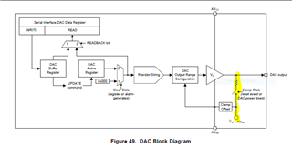
In my lab, amc7836 evm board works in the clamp output mode,the clamp voltage is -10 v;

And when the clamp output‘s ’load current  is -4mA,the the clamp voltage is still -10 v;

But in the datasheet,clamp output impedance typtical value is 8kohm, the max load current should be -10v/8kohm=-1.25mA,

so what's the reason that in fact I can drive the clamp output to -4mA?

  • The AMC7836's DAC output can be in two states:

    1. The output is on and active, where the output amplifier is driving the voltage. In this mode the output can source or sink 15mA (typical), assuming it has sufficient supply headroom. For example, if the DAC was set to -8V or lower, but you only had a -8V AVSS supply, then it could not sink 15mA. The output impedance would look higher during that mode because the amplifier is not in the linear region. If the output was set to -8V and VSS = -11V, then we would expect ±15mA as the output is in its linear region.

    2. the other mode is "clamp mode" In which the DAC output amplifier is disabled and instead there is a switch that sets the output to be connected to AVSS through a current limited switch.  We describe this impedance as being ~8kΩ in the datasheet, but it can vary. So depending on what mode the customer's output is in, we might see less than 15mA sink capability.  The 8kΩ is a typical value, but it can vary depending on the VSS voltage and the DAC load voltage.  I would expect it to be in the range of 1kΩ to 10kΩ.

  • Even if the clamp output impedence is the minimum 1Kohm, when the load current is -4mA and clamp voltage is -10v, the dac output clamp voltage should be -6v ;But it still is -10v, so the impedence is less than 1Kohm?

  • And in clamp mode,why  through a current limited switch.?This may result in small load current

  • I am not sure I understand your question.  The purpose of the clamp circuit is to provide a current path for load capacitance to discharge to VSS during startup, shutdown, and alarm events.  We would not expect the clamp mode to be used against an active load. 

    So if you were to connect a resistor to GND and the output, you might see a constant current that can vary unit to unit.  But if you have a cap load on the output, you should see it eventually discharge to VSS.

  • When the dac is used for GaN transistor nagative bias,there is small current ,may be  -5mA;The greater the power, the greater the current;

    So when dac is switched to clampmode,the out voltage may be pulled high;It is dangerous;

  • My understanding is that the GaN PAs only induce the sinking current when the voltage bias is in the valid Vgs "on" voltage.  When the bias voltage is near the pinch, the current is no longer present.  This solution has been used for many GaN PA bias applications, and I have not seen this current limit as a problem.

  • If the length is 34mm,the GaN gate  current may be 3.4mA even the transistor is pinched off;