This thread has been locked.

If you have a related question, please click the "Ask a related question" button in the top right corner. The newly created question will be automatically linked to this question.

ADS131E08EVM-PDK: The collected data is incorrect

Part Number: ADS131E08EVM-PDK
Other Parts Discussed in Thread: TMS320C6678, ADS131E08

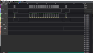
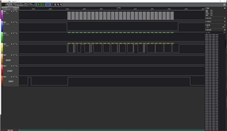
1、After the SPI communication is normal, the register of ADS is configured as follows:CONFIG1=0x92, CONFIG2=0xE0, CONFIG3=0xC0, FAULT=0x00, CHnSET=0x10(n=1-8);

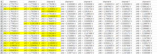
2、Then, EVM is used to measure the output of linear power supply (its output voltage is 1.778V measured by multimeter), and EVM channels 1, 2 and 3 are used to measure, and the other channels are not connected.

      After measurement and conversion, it is found that sometimes the measurement data is wrong, may I ask what may cause this?

  • Hello Zhen,

    Thank you for your post.

    How are you reading and exporting this data? Are you using the MMB0 motherboard and the EVM LabVIEW GUI? Or are you communicating with the ADS131E08EVM daughterboard with your own controller board and software?

    Regards,

    Ryan

  • Hi Ryan

    Thank you for your reply.

    I use TMS320C6678 to control ADS131E08EVM to obtain data. I've successfully read and configured the registers before. After code conversion, the data is displayed on the CCS console. And then I put the results in Excel, and then you see the picture. 

    -Best,

    Zhen

  • Hello Zhen,

    My suggestion would be to analyze the SPI communication using a logic analyzer. Specifically, you will need to capture DRDYn as well as CSn, SCLK, and DOUT. It's possible that the SPI frames are overlapping the next DRDYn interrupt, causing the channel data to be overwritten with new data. On the ADS131E08, each new conversion result is preceeded by a 24-bit STATUS word, which always begins with 0xC0 in the MSByte.

    Regards,

    Ryan

  • Hi Ryan

    Now I set up the internal test signal to verify the ADC.

    The first picture is my initial configuration (SDATAC-WREG register-RDATAC). The second picture captures the returned data, and it can be seen that MSB does start with 0xC0. But this data is converted to voltage instead of the preset 1mV.

    -Best,

    Zhen