This thread has been locked.

If you have a related question, please click the "Ask a related question" button in the top right corner. The newly created question will be automatically linked to this question.

ADS8508: Selecting Capacitors for CAP, REF, VANA

Part Number: ADS8508
Other Parts Discussed in Thread: ADS8505, , ADS8509

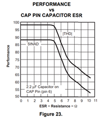
In an application using the ADS8508IBDWR, there seems to be some disturbances to the output digital codes.
Investigating has shown the issue might be related to the tantalum capacitors selected.

1) Are Tantalum capacitors truly needed - as the DS indicates for CAP, REF, VANA?
2) If they are required, are there any parameters besides capacitance that need to be considered?

Regards,
Darren

  • Hello Darren,

    The REF and VANA pins can use ceramic capacitors, and should provide better performance than tantalums.  However, the CAP pin is sensitive to the total ESR.  The datasheet recommends a maximum ESR for the capacitor on the CAP pin of 3ohm.  Many tantalum capacitors will have a value higher than this.  You may want to use a lower ESR tantalum, or use a ceramic capacitor in series with a 1ohm resistor to more closely resemble a high quality, low ESR tantalum capacitor.

    Regards,
    Keith Nicholas
    Precision ADC Applications

  • Hi Keith,

    Sorry to Necro this post.

    But I found this E2E post (5yr old) that says, for the ADS8505 (16-bit version of ADS8508?) the Tantalum on the CAP pin is not necessary; and that a ceramic capacitor is fine. This is because the ADS8505 design isn't as dependent on the ESR. In that post, "Wu JW" indicated, and my customer has also confirmed, that using low-ESR ceramic capacitors on CAP actually results in better ADC SNR. Looking at Figure 17 in the datasheet (ADS8505) shows SNR pretty stable across ESR as well.

    For my customer, actually adding ~1Ω in series resistance to the ceramic capacitor reduces performance slightly.

    But, contradictory to the above...
    I found this document for a dedicated reference that trys to show ceramic-vs-tantalum for reference voltage;
    but it recommends ~1.5Ω of ESR and tantalum as well.

    To summarize the questions:

    1) What is the reason (with details on the mechanism & graphs if possible) we "require" tantalum for ADS8508/9?

    2) I understand that if the ~1Ω ESR is necessary, that "too little" and "too much" can be a bad thing to noise and stability. Why? 
    From my experience, it seems the following are the two issues...thoughts?
    a. Too little ESR and the reference output buffer can't drive the 2.2uF capacitor; resulting in stability issues
    b. Too much ESR and you pull the pole in and lower your phase margin, resulting in stability issues

    Regards,
    Darren

  • Hi Darren,

    The reason a tantalum capacitor was recommended in the datasheet is because 2.2uF ceramic capacitors were not widely available in a small package when the ADS8505 was originally released.

    Since tantalums were commonly available, regulator circuits were typically internally compensated to work with a range of ESR so that many tantalum capacitor types could be used.  In this case, my recommendation was conservative since I was not certain that the CAP pin would remain stable with 0Ohm of ESR.  The older post that you found does confirm that this specific ADC does not require an external ESR capacitance.

    So yes, in the case of the ADS8505, ceramic capacitors can be used in place of all tantalum capacitors.

    Regarding the specific questions, if the ESR is too low and there is not internal compensation, the external capacitance will create a pole with the output stage impedance, reducing phase margin that can result in additional ringing or full oscillation.  Again, this can be eliminated with internal compensation, which is how most modern references and LDO's are designed.

    Depending on how the compensation is setup inside the device, too much ESR can also cause stability concerns, but more commonly, the capacitor will simply not help maintain a steady output voltage with large load transients.

    Regards,
    Keith

  • Hi Keith,

    So yes, in the case of the ADS8505, ceramic capacitors can be used in place of all tantalum capacitors.

    The customer really needs a comment regarding ADS8508/ADS8509.
    Figure23 from your first reply to me indicates SINAD / THD are optimal / stable even down to 0Ω ESR.
    The datasheet is also only saying "it is critical to keep ESR under 3Ω" - which aligns with that Figure23.

    Given this, and correct me if I'm wrong, but I'm understanding that as long as ESR is stable (<3Ω) over PVT and lifetime, then there is no minimum requirement and MLCC are a viable, high-performing stable option today; which they might not have been 15 years ago.
    Am I understanding this correctly? (I guess there is still the issue about vibration noise pickup in ceramics vs tantalum though...)

    If, on the off-chance this device really does require some minimum ESR (not defined in the datasheet or Figure23 from that first post above), then could you confirm for the customer what the required minimum ESR is for stability / operation of the device?

    They pointed out if the only real care-about between MLCC and Tantalum was adding a series resistor for MLCC, then designing for that 1~3Ω sweet-spot is marginally difficult.

    They also confirmed lower-ESR (MLCC) performs better than Tantalum or MLCC + 1Ω resistor.

    Regards,
    Darren

  • Hi Darren,

    Figure 23 in the ADS8509 datasheet does indeed show that the ESR can be 0ohm, so the customer is safe to use a 2.2uF ceramic capacitor in place of a tantalum capacitor for both the ADS8509 (16bit) and ADS8508 (12b version) ADC's.

    Yes, your understanding is correct.  I hope this helps clear things up.

    Regards,
    Keith

  • Hi Keith,

    I need one final thing.

    From Figure 23 in the ADS8509 datasheet we can see that SNR degrades as ESR gets larger.
    Could you provide me a technical explanation as to why this is the case?

    I know the summary is "higher ESR creates a pole (RC) that affects the gain/phase curves; affecting stability".
    I am being asked for an explanation of the mechanism at play here; any further details / light you can shed on this would help put this topic to rest.

  • Hi Darren,

    As the ESR increases, the phase margin for the reference buffer decreases, which takes longer to settle.  The reference input for the ADC is a switched capacitor, and the reference buffer sees this as a step input load current change.  With lower phase margins, the CAP pin will ring and take a long time to settle, which will show up in the ADC spectrum as harmonic distortion, reducing both THD and SINAD.

    The TI Precision Labs - ADC series discusses these effects in more detail.  Take a look at this presentation that discusses the use of a buffered reference.  In the case of the ADS8509, the increased ESR reduces the effectiveness of the buffer, resulting in higher distortion.

    https://training.ti.com/sites/default/files/docs/overview-reference-drive-topologies-presentation.pdf

    Regards,
    Keith