This thread has been locked.

If you have a related question, please click the "Ask a related question" button in the top right corner. The newly created question will be automatically linked to this question.

ADS1256: ADS1256 DATA CONVERSION

Part Number: ADS1256
Other Parts Discussed in Thread: INA333

Hello,

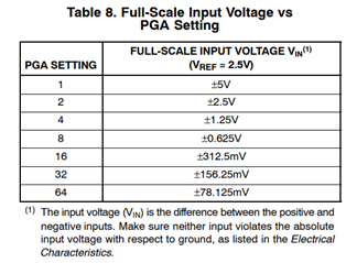
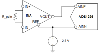
i am using ADS1256 to read the pressure sensor data and here my ADC is working fine with 0-5V pot. now i wanted to test with the pressure sensor in differential inputs but i need to map the maximum voltage to 104.32mV only so before its 0-5V and i need to map this to 0-104.32mV so for that in the firmware side i changed the ref voltage to 0.05321 V =104.32/2*1000 with this calculation but i couldn't get proper raw counts for this like

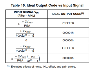
for example 0-5V its 0-8388607 and i want same for 0-104.32mV but when i input 0.1V i mean 100mV  its giving  only 1962161 only so how can i map both raw count and final output voltage.??

please help me to resolve this .

thank you.

  • Hi sagar m,

    The ADC codes are mapped to the ADC full-scale range (FSR), which is 2*±VREF/gain. Assuming VREF = 2.5V, the table below shows what the FSR voltage is across all of the available gains in the ADS1256.

    If your maximum input signal is 100mV, then you would need to select a gain of 32. This means that the maximum positive code (8388607) will be achieved when your differential input signal is 156.25mV. If your maximum input signal will only be 100mV, then your maximum ADC output code is (100 mV / 156.25 mV )*8388607 = 5368708

    This is best you can do with the ADS1256 integrated PGA and FSR. You could always reduce your reference voltage to reduce the FSR, but I don't think is going to help your system too much in terms of noise performance, etc. Another option would be to use an external gain stage that has a gain of 50, which will give you an FSR of 2*±2.5/50 = ±100mV. If you choose this option, you might consider adding some headroom to your system in case your input signal exceeds 100mV.

    -Bryan

  • Hello Bryan thanks for the reply, yes its working when  changed the gain to 32 its varying from 0-150.25 mV but

    1.Can i map exactly  to 104.32mV.??

    2.Can i use different gain for different channels.??

    3. Can i use at a time both differential and single ended 

    4.Based on my knowledge if we use differential the raw count varies from -8388608  to 8388607 and for single ended it should vary from 0-16777215 right ??

    but when i work with 5V pot its showing only 0-8388607 counts for single ended is it correct or is there any changes need.??

    please let me know  for more info.

    thank you.


  • Hi sagar m,

    Answers to your questions are below:

    Can i map exactly  to 104.32mV.??

    As I mentioned in my last post, you could always reduce your reference voltage to reduce the FSR, but I don't know why you would do this. Attenuating the reference voltage will likely add noise and error, so this will often make your system performance worse. Another option would be to use an external gain stage that has a gain of 50, which will give you an FSR of 2*±2.5/50 = ±100mV. If you choose this option, you might consider adding some headroom to your system in case your input signal exceeds 100mV.

    Can i use different gain for different channels.??

    Yes, just make sure to use a gain setting that does not increase your input signal beyond the ADC's full scale range. Write to the ADCON register to change the ADS1256 gain

    Can i use at a time both differential and single ended

    The ADS1256 is a multiplexed ADC, so you cannot measured two channels at the same time. However, you can have a mix of single-ended and differential signals, and the ADC can measure them as needed. The ADC always measures the differential voltage between the analog input you have selected for PSEL and the analog input you have selected for NSEL (see the MUX register). If the voltage on NSEL = 0V, this is a single-ended measurement

    Based on my knowledge if we use differential the raw count varies from -8388608  to 8388607 and for single ended it should vary from 0-16777215 right ?

    This is incorrect. The ADS1256 has a binary two's complement coding scheme. A positive differential voltage would give you a code in the range from 0 to 8388607, while a negative differential voltage gives you a code in the range from -8388608 to 0. There is no option to change the code range to unipolar from two's complement

    -Bryan

  • Another option would be to use an external gain stage that has a gain of 50, which will give you an FSR of 2*±2.5/50 = ±100mV. If you choose this option, you might consider adding some headroom to your system in case your input signal exceeds 100mV.

    Hello Bryan thanks for the reply,

    If you don't mind can you explain it deeply like how i can use  external gain like is that i need to add some extra hardware circuit or else.

    This is incorrect. The ADS1256 has a binary two's complement coding scheme. A positive differential voltage would give you a code in the range from 0 to 8388607, while a negative differential voltage gives you a code in the range from -8388608 to 0. There is no option to change the code range to unipolar from two's complement

    -Bryan

    Ok. actually i will explain the exact application may be that would be the easy thing for you to give solution. in my project i want read the data of differential pressure sensor and pressure sensor since i have used differential channel reading for differential pressure sensor A0 & A1. and two pressure sensor as a single ended so for differential its varying from 0-8388607 for positive full scale and negative its like -8388608 to 0 .and its working fine but i need raw count for single ended is 0-16777215 is that possible .??

  • Hi sagar m,

    Yes, you would need to design an external amplifier stage with your desired gain. A basic device would be something like an INA333, which is an instrumentation amplifier (you can also build an instrumentation amplifier using discrete amplifiers). Texas Instruments has many other amplifiers to choose from, so I would recommend looking through the available devices at TI.com to find one that meets your requirements.

    The INA output is usually pseudo-differential. In other words, the voltage on the VOUT pin is referenced to the REF pin. The voltage on the REF pin can be referenced to ground or to some other voltage. In your case, I would recommend 2.5V assuming you will not be using the ADS1256 internal buffer. The connection diagram would look something like the image I have drawn below

    Your differential input signal will be applied to the INA at IN+/IN-. The INA will gain up the differential input signal and output an amplified signal on VOUT relative to the voltage at REF. If the voltage at VOUT is >REF, the ADC will measure a positive differential input. If the voltage at VOUT is <REF, the ADC will measure a negative differential input. This is how you are able to come closer to using the full range of ADC codes.

    You can also use a pseudo differential measurement to allow a single-ended signal to use the entire range of ADC codes (±FS). Note that the voltage on AINN might need to be different depending on the single-ended output from your sensor. But I leave that to you to figure out, since it is the same operating principle as the INA and as shown in the diagram below

    -Bryan

  • Thank you so much Bryan, i will try this for different gain and actually today i tried for single ended with 5V pot by connecting A0 to the ADC  and here is the code for raw count data reading and 

    static int32_t ads1256_read_result(void)
    {
        int32_t read = 0;
        uint8_t buf[3];
    
        ads1256_write_cmd(CMD_RDATA);	/* read ADC command  */
    
        ads1256_delay_us(10);	/*delay time  */
    
        /*Read the sample results 24bit*/
        while( HAL_SPI_Receive(&hspi2, buf, sizeof(buf), SPI2_HANDLE_TIMEOUT) != HAL_OK );
        read = ((uint32_t)buf[0] << 16) & 0x00FF0000;
        read |= ((uint32_t)buf[1] << 8) & 0x0000FF00;; /* Pay attention to It is wrong   read |= (buf[1] << 8) */
        read |= buf[2];
    
        /* Extend a signed number*/
    
    //    read|=0x800000;
    //      if(read > 0x800000)
    //      {
    //      	read-=16777215-read;
    //      }
        printf("before_raw:%ld\t",read);
        read|=0x800000;
        if(read > 0x800000)
        {
        	read-=16777215-read;
        }
    	printf("raw_data:%ld\t",read );
    
        return (int32_t)read;
    
    }

    this is for voltage conversion 

    static int32_t ads1256_conv2uv(int32_t adc_result)
    {
        /* Vin = ( (2*Vr) / G ) * ( x / (2^23 -1)) */
    	int gain=0;
        float voltage_uv =  ((float)adc_result)*ADS125X_VREF_VOLTAGE/8388607.0;
        printf("gain:%d\t",(ads125x_conf.gain));
        if((ads125x_conf.gain) == 0)
        {
        	gain=1;
        }
        else if((ads125x_conf.gain) == 1)
        {
        	gain=2;
        }
    	else if((ads125x_conf.gain) == 2)
    	{
    		gain=4;
    	}
    	else if((ads125x_conf.gain) == 3)
    	{
    		gain=8;
    	}
    	else if((ads125x_conf.gain) == 4)
    	{
    		gain=16;
    	}
    	else if((ads125x_conf.gain) == 5)
    	{
    		gain=32;
    	}
    	else if((ads125x_conf.gain) == 6)
    	{
    		gain=64;
    	}
    	else
    	{
    		gain=1;
    	}
        voltage_uv /=gain;
        voltage_uv *= 1000000;
        return (int32_t)voltage_uv;
    }

    and i got output varying from 0-5V with raw count from 0-16762165 so  i got confused is this correct or not ??

    and i got some answer in TI forum like for negative full scale need to add 800000h and it give 000000h the for 0 add 800000h  then it gives 800000h then for positive scale need to add 800000h then it give FFFFFFh so its like varying 0-16777215 .

    So please this is the final doubt i had i hope you understand my situation 

    thank you.


  • Hi sagar m,

    The table below shows how the input voltage can be mapped to the ADC output code for the ADS1256. As the datasheet states, these values are encoded using a binary two's complement scheme. Therefore, if you convert these code values from hex to decimal, you see that:

    • 7FFFFFh = 8388607
    • 000001h = 1
    • 000000h = 0
    • FFFFFFh = -1
    • 800000h = -8388607

    So when your ADC outputs FFFFFFh, the input voltage to the ADC is a very small, differential negative voltage. It is not 16777215. That is why you must perform the sign extension in your software, to ensure that you are interpreting the data correctly i.e. to make sure you are reading negative differential voltages as negative.

    Let me know if anything else is unclear.

    -Bryan

  • Thank you so much Bryan, for different gain changes its clear.

    For differential it's ranges from  -8388608 to 0 (-ve full scale) and 0-8388608 (+ve full scale) right.

    For single ended if i used 0-5V pot it ranges from 0-8388608 , if input is negative we can convert it by signed conversion that's all right

  • Hi sagar m,

    You are correct about the differential range.

    For a single-ended input (where the ADC AINP pin is connected to some positive voltage and the ADC AINN pin is connected to ground), there shouldn't be negative voltages. The only case where you should be measuring negative differential voltages is if you use a pseudo-differential input where the AINN pin is connected to some fixed voltage e.g. 2.5V.

    Also, in both cases, you need to sign-extend the output for differential or single-ended

    -Bryan

  • For a single-ended input (where the ADC AINP pin is connected to some positive voltage and the ADC AINN pin is connected to ground), there shouldn't be negative voltages.

    Ok, if i used single ended with 0-5V pot  wiper pin to AINP and AINN id gnd then what will be the raw count.??  

  • Hi sagar m,

    You will be able to use 1/2 of the code range, or 0-8388608 as you stated previously.

    The only way to use the full code range when the sensor output is single-ended is to change the ADC input to a pseudo-differential measurement. I described this in my previous post about the INA.

    -Bryan