This thread has been locked.

If you have a related question, please click the "Ask a related question" button in the top right corner. The newly created question will be automatically linked to this question.

DAC8740H: DAC8740HRGET

Part Number: DAC8740H

Hi ,

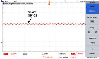
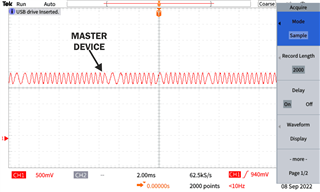
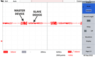
I am implementing HART communication protocol in my two devices let say Master and Slave both are working on 1200 baud rate and odd parity , every time Master sends  request  query Slave gets each and every packet but when Slave sends response to master it miss some packet or changes some bit for example( i am  sending HART in ascii i.e to 0x48 0x41 0x52 0x54 but at master is receiving to 0x48 0xC1 0x52 0x54 ).

I have checked on digital scope may be the change in waveform ? I have attached photos of scope please check an let me know .

also attached schematic i am refereeing for both device .

Please let me know where i am doing wrong .

   MASTER SCH.PDFSLAVE SCH.PDF

  • Ankush,


    I'm not sure exactly what the problem is, but there are a few things to check.

    First, on the schematic, MOD_OUT for U4 on the slave schematic should have a parallel connection to ground through a 5nF-22nF capacitance. I would use a 10nF capacitance there. Second, on the master schematic, There is an added capacitance to ground on the loop. I'm not sure it causes a problem, but I would check by removing C43. I would try to make these modifications to the schematics. I didn't see any issues with the rest of the schematic.

    Looking at the plots, the slave device transmission appears to have a different magnitude between the 1200Hz and 2200Hz signals. This is the first of the three plots that you show. Where is this measured? If this is after the output of U3 (on the right of C2), then perhaps the high frequency of the filter pass band is a little low. I would try increasing the capacitance for C32, and make that several orders of magnitude larger. Try something like a 2.2uF capacitance.

    Along the same line, what are the errors that you see? For the example you gave, it appears that the error is changing a 0 to a 1 in the first bit of one of the bytes. Are the other errors that you see the same? I wanted to know if the error occurs more with a transmission of 0s than with ones.

    These are a few things to check and to try.


    Joseph Wu

  • Hi joseph ,

    Thank you for reply ,I will do changes that you suggested in schematic and check .

    but i have some confusion about your statement "If this is after the output of U3 (on the right of C2), then perhaps the high frequency of the filter pass band is a little low " , I did not get what it means? 

    And yes their are changing  in  bits other than that also, that was just a example to explain .

    Also their is one more question in slave schematic  I have used some protection circuit for example reverse polarity Diodes D24 and many other.

    may be because of that ??? I do not know !!! why slave device magnitude is small and master device magnitude is little big .


  • Ankush,


    I'm sorry, I was looking at a similar schematic and referenced the wrong device numbers. I had meant to check the output of one of the master schematic. On yours, the C66 (not C32) is already 2.2uF. Another thing to try would be to similarly increase the value of C36 to see if the HART signal increases.

    Because the HART transmission is filtered and the output is sent through a filtering network including a DC blocking capacitor, it is important these values are correct. Normally this filtering is some passive band-pass filter that goes from about 1kHz to 2.5kHz. My thought was that because the signal looks different between the 1.2kHz and the 2.2kHz frequencies, the high side of the band-pass filter is too low and there's a large shift in the signal magnitude between the two frequencies. This could be because a capacitor is too large, or because there is extra capacitance somewhere else.

    As for the other diodes on the board, I don't think that D24 would affect this filtering. However, you can test it by shorting the diode. I don't think the other TVS diodes would affect the signal either, but you can also test those TVSs by removing them.


    Joseph Wu

  • Hi joseph ,

    1>I have checked changes you have given by you ,I have changed in slave schematic  increasing capacitor value of C36 it is not working ,I have added one capacitor @ MOD_OUT to the  Ground but result is same .

    2>than I have removed some capacitor (like C26 ,C27 ,C28) which are coming in the path of HART communication ,after removing my waveform's magnitude increases upto 450-500mV peak to peak .but sill my communication are not working properly .

    3> than I have changed microcontroller's crystal from 32.768 KHz to 4MHz but my baud rate is same 1200 and odd parity and now it is working fine .  

    I have conformed it by repeating  the steps to other Boards also it is working fine .

    now my question is that capacitor I have removed is it going to give any kind of trouble in future .

    and also is by changing in crystal  frequency really works .??

    And thank you for you support so far .

  • Ankush, 

    Just to be sure, are C26, C27, and C28 removed from the boards that finally worked? And in the end, the change for the microcontroller crystal caused the communication to work?

    I'm not sure what would cause that to be the problem. Did the HART communication sinusoids change magnitude as well? I just wanted to see if the capacitance change caused the HART signal to become larger through the filter.


    Joseph Wu

  • Joseph ,

     I have removed capacitor ( C26, C27, and C28 ) increases my sinusoids magnitude at that time it wouldn't work .by changing Crystal from 32.768kHz to 4MHz  it is working fine .

    after that  I have again assembled capacitor my waveform's magnitude decreases to 250 - 350 mVpp peak to peak  but sill the communicating properly 

    but when I connects it into multidrop configuration it is not working , than I have again assembled those capacitor . it is working fine in multidrop mode .

    now I am able to connect multiple slave to one master  .

     I just want to ask few more question is how many slave I can connect to single Master is their any rules or guideline for it  in hardware as well as in software .

    and how long can I connect wire  in between master and slave ?? .

     Is load resistor is required to be precision or higher wattage to smooth communication  ?? 

  • Joe will get a response to you soon.

  • Ankush,


    The questions you ask relate more to the HART protocol than to the TI device that you have asked about. This information is should be searchable on the internet.

    The number of devices in multi-drop mode that is supported by the HART protocol depends on the version. HART versions 3 to 5 support polling addresses, while HART revision 6 supports addresses 1 to 63 and HART revision 7 supports addresses 0 to 63.

    The theoretical limit for HART communications is 10000ft, but the cable capacitances will affect this distance and make it shorter.

    The load resistor in a 4-20mA loop reacts with the current sent by the transmitter as a variable. In that sense, the resistance should be an accurate resistance that has low drift (or is larger so there is less self heating). However, the load resistance accuracy isn't going to affect the operation of any HART signal much.


    Joseph Wu

  • Thank you so  much Joseph so far .