This thread has been locked.

If you have a related question, please click the "Ask a related question" button in the top right corner. The newly created question will be automatically linked to this question.

Read Device ID

Other Parts Discussed in Thread: ADS1298, CC2500

Hi

(Tom, hopefully you can see my thread, I have been working hard to solve the read id version problem, so hopefully you can see my effort and willing to help me again.)

The problem is still trying to read the output from ADS1298, and in fact, I think it keeps return me 00001111 no matter what I send to it, even though I sent out SDATAC, I observed this 00001111 output at DOUT.

Here is my set up:

ADS1298: AVDD 3V, DVDD 3V from 2 x 1.5V AA batteries

RF2500, powered by its battery pack, 2 x 1.5V AA batteries

Also, there is only power and digital connection attached with ADS1298, no any capacitors, as I had designed a PCB board which seems to burn down the chip. However, I tried to keep all the flywires as short as possible, especially those for SPI.

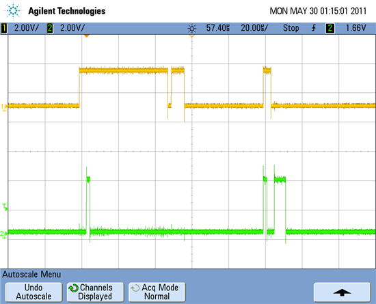
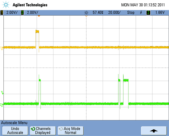
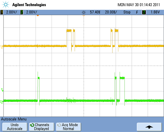
Now I have a better oscilloscope allow me to capture some pictures, and here are some evidences,  SCLK  = 4MHz.

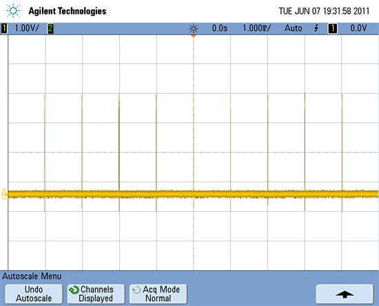
SCLK (Top) and DIN.

.

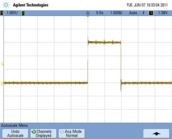
 Here is SCLK (Top) and DIN, while I was sending READ DEVICE, 20h, SINGLE BYTE, 00h, DUMMY DATA, 9Ch.

 This is SCLK with DIN, and DIN is 0Ah, which is STOP


.

This is one example of SCLK and DOUT, at the time I sent out STOP command.

SCLK and DOUT,  evidence of the constant 00001111, so whenever I send a command over, in this case 20h (Write register 1), 00h (Single byte), 9Ch (Dummy data), I keep having the constant 00001111 as a return from DOUT.

 I am still trying to see how I can capture the moment of the start up sequence, perhaps someone can give me a hint.


Thanks all

  • Hi Weng Kou Chan,

    Take a look at the 'Files' tab here on the Precision Data Converter forum.  There is a zip archive there with a number of screen captures that you may find useful, these were taken with a logic analyser (the Intronics Logic Port - a great tool by the way) so the detail is pretty clear.  You've been working with Kevin on the hardware issues that 'burn down the chip' to some extent.  We can't really help you there, so I suggest you have your board reviewed by someone locally to go over your connections and layout.

    The SDO in your pictures above seems wrong to me.  If you are powered from 3V, the SDO should have voltage output approaching 3V - your scale is 500mV and you barely have one division, this is not how the part should work.  The amount of noise you have in your screen shots and the issues with 'burning chips' are most likely all related with incorrect power and grounding between your RF2500 and ADS1298 boards.  Please correct and post your schematic here and we can take another look.  The first version I saw uses a schematic symbol for a micro controller and we don't have the bandwidth to review the pin to pin conversion and verify your connections for you.   Please also describe exactly how you have the two boards connected together.

     Josh Wojnas has put together some hardware that sounds very much like what you are trying to do here.  You might try looking through this post as well:

    http://e2e.ti.com/support/data_converters/precision_data_converters/f/73/p/43772/218128.aspx#218128

  • Thank you Tom, really appreciate you still have the patience to me.

    Regarding that voltage of the second channel, I did realise it is wrong, as the voltage is too small, so what I did was to check the other pins surround the pin I measured, and see whether it is a noise from the surrounding, like some crosstalk, but it wasn't.

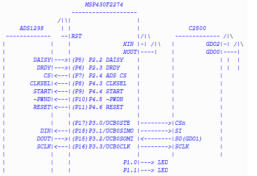
    Then I disjointed the RF2500 and the ADS1298, and run my code on it just to check is output at each pin. The code I run was to initial the SPI pins, and asked it to write something into ADS1298. I noticed that the MOSI is sending out the correct data, SCLK is running at the correct speed, and also SOMI is at zero volt.

    I would like to confirm the behaviour of the signal at DOUT from ADS1298, does it go high only when it is sending meaningful data please?

    By the way, I think I 'fixed' that constant periodic signal at DOUT, so the signal at DOUT becomes random again when I put the read version function in the while loop.

  • OK - perhaps now I understand what the issue really is here - are you connecting your ADS1298 directly to the eZ430-RF2500T target board (Figure 10 of SLAU277) via P15-P18?  If that is the case then have you physically removed the CC2500 chip from the PWB? 

    At a minimum, you are going to have to GPIO control the UCB0STE line and ensure the CC2500 CSN is held high when trying to talk to the ADS1298.  You may be able to use one of the P2.x pins on that breakout for /CS to the ADS1298.  The DOUT from the ADS1298 will only go high (output meaningful data) when it has a proper /CS low, proper SCLK and proper command sent to its SDI.

  • yes, as you said, I am connecting the ADS1298 to the RF2500 directly.

    In my SPI setup, I have sent P17 high all the time to disable it, I didn't physically remove it from the board.

      //Disable CC2500 onboard

      PORT_SPI_DIR |= BIT0;

      P3OUT |= BIT0;

    When I talk to ADS1298, I set the CS pin low, otherwise high. The DRDY and DOUT from ADS1298 keeps giving me random signal, even though I had the same function to run in the while loop in main, and I expected to see some periodic pattern.

  • Take a closer look at the SDO on your last two screen captures and double check that CSn on the CC2500 is really being held high.  If this is SDO, it is probably coming from the CC2500 and not the ADS1298.  The CC2500 uses the rising edge of SCLK as the valid data strobe and drives data out on the falling SCLK edge.  The ADS1298 has the opposite clock to phase relationship (drives output on rising).  The last picture is actually 0x1E, not 0x0F and you can see pretty clearly that data is driven with the falling SCLK in the screen capture of SAT MAY 28 23:13:44 2011.

    Above all, you MUST have good ground connections between the two boards.  Make sure (P1) is connected back to DGND on your ADS1298 board.

  • Thank you Tom.

    Firstly, I do have the CSn on the CC2500 being held high all the time, as I never have a code to select it back.

    My set up is, ADS1298 has separate digital ground and analogue ground, and I have put 2 x 100nF capacitors on each analogue and digital power rail to minimize some noise. The RF2500 is still powered by USB, and the GND is connected to the ground of digital.

    Here are some evidences of the random data I get for the same command, I expected to see 92h on DOUT at the time 9Ch on DIN.

    Top yellow: DOUT, Bottom green: DIN with data 20h, 00h, 9Ch

    Once again appreciate your generous help.

  • Good morning Victor, I take it the scope has only two channels. See if there is a 'reference' option and try to include your /CS in there as well. Show us SDO with respect to SCLK and SDI, also with respect to SCLK. Your analog and digital grounds must tie together, preferably at the ADS1298. Your schematic showed only DGND. The batteries for the RF2500 and ADS1298 should be tied to that net.
  • Thank you Tom. I have got the scope screen printed and zipped in a file1881.scope.rar, hopefully you can open the file without problem.

    The condition that I take these screen was

    ADS1298: AVDD: 3V, DVDD 3V, AGND and DGND tied together, with 2x 100nF capacitors for each power rail for noise reduction.

    RF2500: powered by USB, the GND here is tied to ADS1298's GND, so GND= AGND = DGND

    SCLK = 500kbps

    SPI: CPOL = 0, SPHA = 0

    I have also made sure that there are at least 4 Tclk cycles before taking CS high 

    By the way, I used the output of the internal clock (2.048MHz) to verify that I can write to its register, is there any other register that I can write to and it can provide me some solid physical evidence please? In fact, I tried to set up its internal respiration (Respiration control register), and output the signal (CONFIG 4), but all I got is some noise, and is the same noise for all the frequencies I can set in CONFIG 4. Is it because I misunderstand the way to use it ? something missing?

  • Hi Tom,

    I have got a feeling that the randomness is due to the fact that I execute the instruction wrongly, I have zipped my code, could you please have a look and give me some feedback please? Is not too long, just contain the basic functions

    Also, just a note, my DRDY is random as DOUT.1538.tesing_use.zip

  • Hi Tom

    Have you had a chance to view my code and perhaps able to discover the cause of the randomness of the DOUT please?

    Regards

  • Hi Victor,

    Not yet, but one thing you can do for me is to try and simply 'not read' the device.  Just power up and perhaps do a reset command, you should see a steady data rate by virtue of observing the DRDY pin.  If your SW is not using interrupts to validate reads based on the state of DRDY, you can get 'random' results on both DOUT and DRDY.

  • Hi Tom

    sorry for the absence, I was sick for a week and wasn't able to do anything.

    According to your last advice, I was trying to see the DRDY toggles at fclk/8192 or LP mode with DR = fmod/1024 (on page 78 from datasheet), I powered up both devices, then I did

      init_MSP430_Com_IO ();

      enable_ADS1298_Interrupt ();     

      set_ADS1298_Power_Down ();        // Power Down Pin (ACTIVE LOW)               

      Hard_Reset_ADS1298_On ();         // RESET Pin (ACTIVE LOW)        

      set_ADS1298_Start_Low ();         

      set_ADS1298_Clock_External ();

      Set_ADS1298_Chip_Enable ();       //to set the pin to Low

      set_ADS1298_Power_Up (); 

      set_ADS1298_Start_High (); 

      set_ADS1298_Clock_Internal (); //use internal clock, energy save

    at this point, I expected I was at block 3 and saw the DRDY toggle, but I but i saw nothing.

    However, once I did all the initialization, including configuring the ADS1298, and started conversation, then i observed the output from DRDY, and here is what I got.

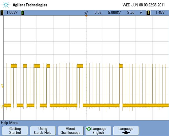
    DRDY has a pulse every 1 ms, is that because I set the sampling rate to be 1kSPS?

    Here is a zoom in, the pulse width of the DRDY is 2us.

    Now, I assume I can receive the 'correct' data, so I do the processing in my while loop


        if (ADS1298_Status_Flags.ADC_Data_Ready == SET)  //ADS1298_Status_Flags.ADC_Data_Ready is set by the interrupt from DRDY

        {

          //For timing

          SetBit(PORT_LED_DIR, RED_LED);

          SetBit(PORT_LED_OUT, RED_LED);


          Set_ADS1298_Chip_Enable ();                              // Set the Chip ENABLE to start the SPI transaction

          for (i = 2; i < ADS1298_DATA_LENGTH+2; i++)                       // Read ADC Data (status + all channels)

          {

            ADS1298_Data [i] = ADS1298_SPI_Channel_Data (DUMMY_DATA); 

          } 

          Clear_ADS1298_Chip_Enable ();                            // Clear the Chip ENABLE 


          //Time end

          ResetBit(PORT_LED_DIR, RED_LED);

          ResetBit(PORT_LED_OUT, RED_LED);


          //Send to CC2500

          // Build packet

          ADS1298_Data[0] = ADS1298_DATA_LENGTH;       // Packet length

          ADS1298_Data[1] = 0x01;                     // Packet address


          //RFSendPacket(ADS1298_Data, ADS1298_DATA_LENGTH+2);              // Send value over RF


          ADS1298_Status_Flags.ADC_Data_Ready = CLEAR;

        }


    and now DRDY started giving me random pulses again, although I can still see the 2us pulse width and 1ms pulse period pattern in the random waveform sometimes. 

  • Hi Victor,

    Using the DRDY as an interrupt, you must read all data before the next DRDY comes out of the device.  If your reading of data runs into the next DRDY cycle, you will get corrupted data.  Speed up your SCLK or simply try reading without trying to send over the radio - just store it into a buffer and look at the results.

  • Hi Tom

    My SCLK is currently running at 1MHz, with the data rate of ADS1298 set to 1000sps, and I actually didn;t send any data over the wireless channel, but only stored them, as my RFSendPacket was commented out.

    Regarding the steady data rate of DRDY,  I was trying to observe DRDY toggles at fclk/8192 or LP mode with DR = fmod/1024, I followed page 78 up to block 3 and I didn't see anything. However I observed the periodic pulse every 1ms after I set START = 1, which is different to what the datasheet states, fCLK/4096, but I indeed wrote to CONFIG1 to set the data rate 1000SPS in low power mode, so is my observation expected?