This thread has been locked.

If you have a related question, please click the "Ask a related question" button in the top right corner. The newly created question will be automatically linked to this question.

ADS1256: ADS1256 technology support

Part Number: ADS1256

Hi,

We use the ADS1256 in our project and now we have below technology support:

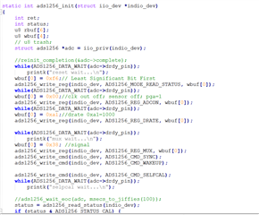
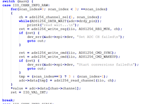
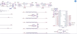
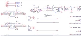
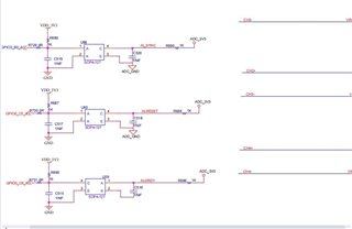
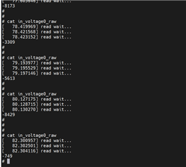
We adjust the input voltage amplitude but the output data is error, and please kindly review the below schematic diagram, programm and testing result, and advise why this result is error thanks.

  • Hi Zhang Liang,

    What signals are you applying to the ADC, and what is the ADC output? I.e. what is the error you are getting?

    Does the issue occur on all channels?

    Have you confirmed that the SPI communication and timing is valid using a logic analyzer?

    Please provide more details about what you want your system to do, the results you are getting from the ADC, and what you have done to troubleshoot this issue

    -Bryan

  • Hi Bryan,

    1. This is the differential signal input, and the data read from the register is right;

    2.We update the 8channels analog signal input to 4 channels differential signal, the result from SPI is -10000+--100000, and this data will no follow up the input voltage;

    3. The reference voltage is 2.048V;

  • Hi Bryan,

    We have other issue for the ADS1256:

    1. What is the Chip ID, we can't get from the datasheet;

    2. How to  confirm when the ADC srart  sampling instant;

    3. If we have any Linux IO subsystem reference programm for our evaluation, thnaks.

  • Hi Zhang Liang,

    Let me rephrase some of my questions:

    1. Can you tell me what voltages you are applying to the ADC, and what is the ADC output code? For example, if you apply 1V to the ADC, do you get an ADC code that is the equivalent of 1V? If not, what do you get?
    2. How much error are you are seeing? I did not understand what this means:
      -10000+--100000,
    3. Have you confirmed that the SPI communication and timing is valid using a logic analyzer?

    I would try applying a known signal from a precision source to determine if you can measure this signal accurately. For example, apply 1V to the ADC inputs and see what you get at the output. You might also try bypassing the resistor divider so you can rule out this source of error.

    Regarding your questions:

    What is the Chip ID, we can't get from the datasheet;

    The chip ID is not provided in the datasheet because these are internal bits meant for identification purposes by TI. It is possible that these bits can be different for different devices, therefore you should not rely on them for anything

    How to  confirm when the ADC srart  sampling instant;

    How are you controlling sampling? Are you using the SYNC/WAKEUP command or the SYNC pin? Either way, synchronization occurs after the START pin is taken high or after the first SCLK used to shift in the WAKEUP command. This is described on page 27 in the datasheet

    . If we have any Linux IO subsystem reference programm for our evaluation, thnaks.

    I am not aware of any Linux support for the ADS1256. I did a quick search on Google and it looked like there were a few git repositories and some Raspberry Pi code available if you want to try those options. However please note that none of these results are tested or endorsed by TI

    -Bryan