Hi Team,
We received this inquiry from our customer.
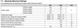
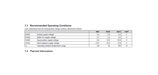
In the datasheet for the ADS8568 it is stated that the minimum voltage levels with which the device will function for HVDD and HVSS are +5V and -5V respectively.
However, looking through the datasheet all input characteristics are specified with the HVDD at +15V. In addition the maximum input voltage is +10V (taking only the positive side).
When the HVDD is reduced to +5V (i.e. the minimum allowable), what is the maximum range of the input voltage for the converter to function correctly? In our case it seems to limit/clamp at around 4 - 4.1V. Is this correct? The part is configured for parallel bus, STARTCONV control and 2x VREF input, with VREF being externally generated at 2.5V value.
I understand that the analog input voltage range are ±4 VREF or ±2 VREF depending on the setting of the RANGE pin.
The ADC is set up for +/-2x VREF operation.
We use an external reference in this application. It is based on a REF5025AIDGK, but it is HEAVILY buffered and stabilised, because of the tendency of the ADC to draw current spikes. on the VREF input. With an external voltage input, we managed to get a flicker of typically +/-1bit (value) out of 65536 with the design.
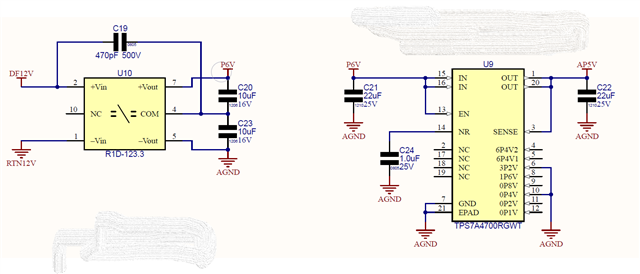
I shall attach diagram sections of the ADC itself, the regulator supplying it and the amplifier channel that drives the ADC input. What is important here, and that was the reason I asked the question w.r.t. the performance of the ADC in these conditions, is that the HVDD of the ADC and the opamp are both supplied from the same regulator set at 5V. So my question is: what happens to the ADC function if the input voltage rises to 4.5V, when the HVDD is only 5V? Will the ADC not in some way malfunction then?
I wanted to add that the ADC itself and the amplifier reside on different boards, but the only intervening devices are gold-plated square-post connectors. The socket is in fact a Samtec brand bottom-entry device.


Regards,
Danilo


