This thread has been locked.

If you have a related question, please click the "Ask a related question" button in the top right corner. The newly created question will be automatically linked to this question.

ADC3683EVM: Use ADC35XX EVM GUI SW to configure CDCE6214 with external reference clock

Part Number: ADC3683EVM
Other Parts Discussed in Thread: CDCE6214, ADC3683

Hello,

In the ADC35XX EVM GUI software for the ADC3683EVM only 2 wire mode is supported by the onboard clock generator IC.
Is there any possibility to use the onboard CDCE6214 for 0p5 wire mode as well e.g. by feeding an external clock signal into the secref input and setting the registers of the CDCE6214 via the ADC35XX EVM GUI SW and the FTDI chip over I2C?
If so, how do I tell the software to set the clock generator IC correctly?

I would like to use the ADC3683 with 0.5-wire LVDS in real decimation mode with a decimation factor of 4, 18 bits and a sampling rate of 65 MSPS.
Is it easier to input the 65 MHz sampling clock and let the CDC multiply it with 4.5 to get the 292.5 MHz DCLKIN or the other way round?

Thank you in advance and best regards,

Lukas

  • Hi Lukas,

    We are working on this for you, and will get back to you in a few days.

    Regards,

    Rob

  • Hi Lukas,

    Is an acceptable solution that we provide you a python script to configures the CDCE6214 via I2C over the FT4232? The python script won't have any functions to set the outputs to arbitrary frequencies ( it will be fixed at just 65MHz and 292.5MHz) however the framework for communicating to the CDC6214 via I2C over the FT4232 will be included, so you can modify the registers on your own at a later time if desired. Please let us know and Amy can package these scripts up for you.

    Regards, Chase

  • Hi Chase,

    yes, please send me the python programm with documentation.
    Is it possible, with some adaption of the code, to generate the 65 MHz CLK and 585 MHz DCLKIN for real decimation with factor 2 and 1170 MHz DCLKIN for bypass mode?

    Best regards, Lukas

  • Lukas,

    Please find python script attached. adc36xx_CDC.zip

    585MHz should be possible if the CDCE can be configured for it. The 1170MHz will not work due to the output drivers of the ADC3683 being limited to 1Gbps.

    Regards, Chase

  • Thank you very much!
    When do I have to run the python script? Should I first setup the ADC via the GUI and then run the Python script?
    BR, Lukas

  • Furthermore I would need a FPGA configuration file for the High Speed Data Converter Pro Software (TSW1400) for ADC3683_0w5_18bit.
    Could you also provide me with this?

    Thank you in advance!
    BR, Lukas

  • Lukas,

    Amy and I are both on travel this week so we won't be able to test it out before sending to you. I can create what I believe will work however there is no way to test it. If that is ok with you, I can do this for you shortly.

    Regarding the configuration sequence, you are correct. You should configure the ADC with the GUI first and then run the python script afterwards.

    Regards, Chase

  • Hello Chase,

    thank you for your quick reply!
    Please send me the possible solution, I will try it out today.

    Thank you, I will try this. I guess I will have to close the GUI before running the python script to free the FTDI-USB port?
    I noticed that in taskmanager even after closing the GUI still some programmes with the same name were running. Is this a bug? Do I have to stop those tasks as well?

    Best regards,
    Lukas

  • Hi Lukas,

    Please try this .ini file.

    Regards, Amyhttps://e2e.ti.com/cfs-file/__key/communityserver-discussions-components-files/73/ADC3683_5F00_0p5W_5F00_18bit_5F00_untested.ini

  • Hi Amy,

    thank you very much!

    Unfortunately the HSDC software also freezes, like with 2 wire and bypass mode (see other thread).

    How do I have to modify the python script to get 65 MHz CLK and 146.25 MHz DCLKIN from the CDC-Chip?

    Best regards,
    Lukas

  • FYI the python script is configured for 65MSPS and 292.5 MHz sample and data clocks, respectively.

  • Hello Chase,

    I know, 65/292.5MHz are appropriate for 1/2-wire and real decimation factor 4, I would like to try out 1/2-wire and real decimation factor 8 with 65/146.25MHz, as this frequency combination already works in 2-wire mode with real decimation factor 2.

    Best regards,
    Lukas

  • Hi Lukas,

    I am checking into the correct register writes to configure the clocking chip. I will get back to you in the next few days.

    Regards, Amy

  • Today I retried taking special care when setting up the ADC in 0p5 wire mode, real decimation 4, setting analog to internal ramp with factor 10, closing the GUI, killing the GUI.exe in taskmanager that prevents running the python script, run the python script the first time (PLL Lock LED stays off), run the python script a second time (PLL Lock LED turns on) and then start HSDC with your untested 0p5wire.ini. I tried both entering 65M left of the cog wheel, as well as enabling with decimation 4, but both times I get either scrambled data or this error message:


    USER_LED2 on the FPGA bord is on, clock signals were measured with oscilloscope to be present.
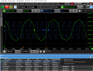
      blue: DCLKIN, green: CLK

    Please advise!

    Best regards,
    Lukas

  • Hi Lukas,

    Thanks for testing this out. I currently have this setup in the lab and I am working on solving this. I will let you know what I find.

    Regards, Amy

  • Lukas,

    Just to add onto what Amy said, I packaged the wrong register configuration in the original zip above. Amy caught this and realized the output is actually just a single 10MHz on output 1 and all other outputs are powered-down. She is working to get the correct register sequence and will provide it to you once finished. This may take a day or so to do so please be patient.

    Thanks, Chase

  • Hi Amy and Chase,

    thank you very much!
    Could you please not only include the sequences for 65 MHz / 292.5 MHz, but also for 16.25 MHz / 292.5 MHz and 65 MHz / 146.25 MHz?

    Best regards,
    Lukas

  • Hi Lukas,

    I have attached the configuration files for Fs=65 MHz / DCLK=292.5 MHz (allows for bypass mode or real dec. by 4) as well as Fs=65 MHz / DCLK = 146.25 MHz (allows for real dec. by 8). You can configure the part using the ADC35XX GUI and then configure the clocking chip via the script. I am having some issues with the ramp test pattern in these configurations. I have confirmed the clocking frequencies are correct, but I am continuing to debug the issue with the test pattern in half wire mode. If you would like to test things out, you should see a ramp test pattern correctly generated in 2w, 18b bypass mode (Fs=65 MSPS, DCLK = 292.5 MHz). I will keep you posted with what I find. 

    Regards, Amy

    0x0038 0x0009
    0x003E 0x0004
    0x0048 0x0004
    0x002F 0x0A00
    0x001E 0x00EA
    0x0005 0x0000
    0x0000 0x1010
    0x0004 0x0040
    0x0000 0x1010
    0x0038 0x0009
    0x003E 0x0002
    0x0048 0x0002
    0x002F 0x0A00
    0x001E 0x00EA
    0x0005 0x0000
    0x0000 0x1010
    0x0004 0x0040
    0x0000 0x1010

  • Hi Amy,

    thank you for the register setting files!


    I tried the following:

    • unplug and replug ADC3686EVM from USB, run ADC35XX EVM GUI (default 2wire, 18bit, bypass, CDC enabled, CLK 65 MHz, DCLKIN 292.5 MHz), click configure then configure CDC, then switch to 0p5 wire mode, real decimation 4 and press configure:
       - PLL_LOCK LED is off, CLK and DCLKIN are both off
      close ADC35XX EVM GUI and kill background process with task manager, run python script with CDC6214_FS-65M_DCLK-292p5.txt once:
       - PLL_LOCK LED stays off, CLK is ~67 MHz and DCLKIN is ~303 MHz
      run python script with CDC6214_FS-65M_DCLK-292p5.txt a second time:
       - PLL_LOCK LED turns on, CLK is 65 MHz, DCLKIN is 292.5 MHz
      run python script with CDC6214_FS-65M_DCLK-292p5.txt a third time:
       - PLL_LOCK LED stays on, CLK is 65 MHz, DCLKIN is 292.5 MHz
    • unplug and replug ADC3686EVM from USB, run ADC35XX EVM GUI (default 2wire, 18bit, bypass, CDC enabled, CLK 65 MHz, DCLKIN 292.5 MHz), click configure then configure CDC, then switch to 0p5 wire mode, real decimation 8 and press configure:
       - PLL_LOCK LED is off, CLK and DCLKIN are both off
      close ADC35XX EVM GUI and kill background process with task manager, run python script with CDC6214_FS-65M_DCLK-146p25.txt once:
       - PLL_LOCK LED stays off, CLK is ~67 MHz and DCLKIN is ~303 MHz
      run python script with CDC6214_FS-65M_DCLK-146p25.txt a second time:
       - PLL_LOCK LED turns on, CLK is 65 MHz, DCLKIN is 292.5 MHz
      run python script with CDC6214_FS-65M_DCLK-292p5.txt a third time:
       - PLL_LOCK LED stays on, CLK is 65 MHz, DCLKIN is 292.5 MHz
    • unplug and replug ADC3686EVM from USB and then just run the python script with the path adapted to one of the three provided register setting files:
       - PLL_LOCK LED stays off, CLK and DCLKIN are both 90 MHz
    • unplug and replug ADC3686EVM from USB, run ADC35XX EVM GUI (default 2wire, 18bit, bypass, CDC enabled, CLK 65 MHz, DCLKIN 292.5 MHz), click configure then configure CDC, then change CLK to 24MHz and click configure and configure CDC again, switch to 0p5 wire mode, real decimation 4 and press configure:
       - PLL_LOCK LED is off, CLK and DCLKIN are both off
      close ADC35XX EVM GUI and kill background process with task manager, run python script with CDC6214_FS-65M_DCLK-292p5.txt once:
       - PLL_LOCK LED turns on, CLK is 24 MHz and DCLKIN is 108 MHz
      run python script with CDC6214_FS-65M_DCLK-292p5.txt a second time:
       - PLL_LOCK LED stays on, CLK is 24 MHz, DCLKIN is 108 MHz
      run python script with CDC6214_FS-65M_DCLK-292p5.txt a third time:
       - PLL_LOCK LED stays on, CLK is 24 MHz, DCLKIN is 108 MHz

    Please advise!

    Best regards,

    Lukas

  • Hi Lukas,

    I set this up in the lab again and had no issues getting the correct frequencies. Here are the exact steps that I followed:

    1. Plug in the ADC3683EVM via USB and launch the ADC35XX GUI

    2. Software reset from the GUI

    3. Select 0.5w, Real, Decimation Factor 4 (or 8). This should automatically turn off the CDC Clock Enable feature.

    -> Note: At this point, the DLL LED on the board should remain off

    4. Click 'Configure'

    5. Close out of the ADC35XX GUI (also ensure in task manager that no process is running in the background)

    6.  Launch the python script

    7. Ensure that the 'config_file_path' is set to the correct path name and desired frequency combination 

    (i.e., CDC6214_FS-65M_DCLK-146p25 or CDC6214_FS-65M_DCLK-292p5)

    8. Run the script. You should only need to run the script once and the PLL LED should light up, indicating that the PLL is locked.

    I probed the sample clock and data clock lines again and confirmed that the frequencies are 65M (Fs) / 292.5 (DCLK) and 65M (Fs) / 146.25 M (DCLK). 

    I am still looking into the test pattern issue and will give you an update soon.

    Regards, Amy

  • Hi Ami,

    I followed your steps:

    1. Plug in the ADC3683EVM via USB and launch the ADC35XX GUI -> done

    2. Software reset from the GUI -> done

    3. Select 0.5w, Real, Decimation Factor 4 (or 8). This should automatically turn off the CDC Clock Enable feature.

    -> Note: At this point, the PLL LED on the board should remain off -> done, PLL LED turns off

    4. Click 'Configure' -> done

    5. Close out of the ADC35XX GUI (also ensure in task manager that no process is running in the background) -> done

    7. Ensure that the 'config_file_path' is set to the correct path name and desired frequency combination 

    (i.e., CDC6214_FS-65M_DCLK-146p25 or CDC6214_FS-65M_DCLK-292p5) -> done

    6.  Launch the python script -> done

    8. Run the script. You should only need to run the script once and the PLL LED should light up, indicating that the PLL is locked. -> done, PLL LED stays off

    Again, only after a second run the PLL LED turns on

    I inserted a print in the loop to see if the data written is the same as in the config file:


    Other than that no modifications to the python script were made.

    We are using Python 2.7.9. Which version do you use?

    Best regards,

    Lukas

  • Hi Lukas,

    I am using Python3. To update you, I am still working with our team to clarify why I saw an issue with the test pattern.

    In the meantime, please try upgrading to Python3.

    Regards, Amy

  • Hi Lukas,

    I have been working with the software team on this issue and now have a solution using the attached .py file below. 

    Launch the ADC35XX GUI and click the 'load' button to load the .py file. This will then allow you to configure the part in 18b, 0.5w, real, decimate by 4 mode with onboard clocking enabled (Fs=65M, DCLK=292.5M). Ensure that you click both the 'Configure' and 'Configure CDC' options. 

    Regards, Amy

    https://e2e.ti.com/cfs-file/__key/communityserver-discussions-components-files/73/cdc_5F00_en.py

  • Thank you very much for your support!