This thread has been locked.

If you have a related question, please click the "Ask a related question" button in the top right corner. The newly created question will be automatically linked to this question.

ADS1248: Wrong output after Self Offset Calibration

Part Number: ADS1248

Hello!

I have a question regarding the self-offset calibration of ADS1248. I need to self-offset calibrate the ADC for my application, therefore I am using the SELFOCAL command for that, but after calibration, my output values are not correct. Following is what I did,

  1. Initialized ADC by writing to MUX0, VBIAS, MUX1, SYS0, IDAC0, and IDAC1.
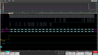
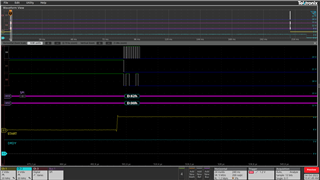
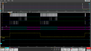
  2. Then I send the SELFOCAL command.
  3. Wait for DRDY to go low. In my case calibration is done in 200ms since the SPS I am using is 80.
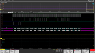
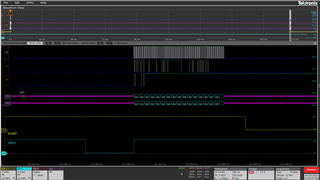
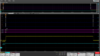
  4. Then I start reading samples from ADC.

If I skip steps 2 and 3 my readings are correct but have offset errors. Also, when sending the SELFOCAL command the differential analog inputs of the ADC are floating, but this should not affect calibration, since the ADC shorts the inputs internally to disconnect from external circuitry if the SELFOCAL command is sent. Kindly let me know what steps should be taken in order to self-calibrate this ADC correctly.

Should the START pin remain high for the entirety of calibration?

Thank You!

  • Hi Rohail Syed,

    Some questions for you:

    1. Can you explain what you mean by "my output values are not correct"? What values are you expecting, and what do you receive from the ADC? If you can provide the raw hex values from the ADC that would be helpful
    2. What is the offset error in your measurement when you skip steps 2 and 3?
    3. After the calibration, can you read back the value stored in the OFC register to see what it is? Please provide this value in your reply, as well as your register settings
    4. How are you controlling START during the calibration process now? You asked if you should hold START high for the entire process, but did not state the behavior of START in your system right now.

    It might also be helpful to see logic analyzer data of your communication before, during, and after the calibration command is issued

    -Bryan

  • Hey Bryan Lizon!

    Replies to your questions:

    1. By output values, I mean the differential voltage measured and sampled by the ADC at its analog inputs. AFTER calibration, I get a 0x3BB758 hex value which when I multiply by the scale (29.8nV), I get 0.116624088, but the expected value is 0x5AB536, which when multiplied by scale (29.8nV) is 0.177149974V and so the error offset becomes, -60.525886mV, which is too high.
    2. Now if I DO NOT calibrate, I get a 0x5AD1AD hex value which when I multiply by the scale (29.8nV), I get 0.1773671266V, and the expected value is 0x5AB536, which when multiplied by scale (29.8nV) is 0.177149974V and so the error offset becomes, +217.1526uV.
    3. Following are the screenshots of register settings, the OFC register values, and the START pin status.

    The above image contains the register settings applied and read back during initialization.

    The above image shows the SELFOCAL command being sent

    The above image shows the Initialization and SELFOCAL command sent. I am using two ADCs that share the same bus so I pull START of ADC1 to low before Initializing ADC2 with the same register values and then I pull START to high again to send the SELFOCAL command.

    The above image shows all the register settings and values after calibration is done including OFC registers.

    The above image shows the zoomed-out version of when calibration is done.

    The above image shows the whole communication. Since my SPS is 80, the calibration should be done after 200.26ms as specified in the datasheet, but when I checked I found it to be about 211.75ms.

    PS. Now if we take our expected value of 0x5AB536 and subtract the OFC value which is 0x1F1292, we get 0x3BA2A4. Now let's scale this value by multiplying by 29.8nV, we get (3908260 * 29.8nV) = 0.116466148V. This means that OFC calculated by the SELFOCAL command is wrong but the hex value at the output of the ADC before the final output in figure 72 of the datasheet is correct. 

    Thank You!

  • Hi Rohail Syed,

    Can you share your schematic? I see that you have the IDACs enabled and outputting 1mA each, and you do not have the internal reference selected as the ADC VREF (but it is enabled for the IDACs). So it will be helpful to see how the system is architected.

    The SELFOCAL only measures the ADC offset. If there are other offsets in your system e.g. before the ADC, they will not be removed by the SELFOCAL command. Have you tried measuring a known, low-noise input signal to see if the ADC can correctly convert this value? I would typically use something like a DP8200 as a signal source, and apply 1V to the ADC inputs then check the resulting code. Then I would incrementally introduce the remaining parts of your system e.g. IDACs, reference resistor, etc., to see if I could identify the source of the error.

    -Bryan

  • Hey Bryan Lizon,

    My design schematic is more or less the same as those described in figure 5 of Application Report SBAA180B and figure 10 of Application Report SBAA201. As you can see that there are no active components in the external circuitry. The external circuitry only includes passive components which are RC filters. Therefore SELFOCAL command should be enough to remove the offset caused only by the input multiplexer inside the ADS1248. On the other hand, the SELFOCAL command disconnects the selected inputs from the internal circuitry and applies a zero differential signal internally, connecting the inputs to mid-supply (Section 9.4.5.3.1 of ADS1248 datasheet), so the external circuitry does not matter. Also, when the SELFOCAL command is not used the output value of the ADC is very close to the expected value (OFC registers = 0x000000) at the input of the ADC, but when SELFOCAL is used the output value is far from the expected one (OFC values loaded by the ADC itself after SELFOCAL command), which is quite weird. Following are the schematic screenshots of the figures mentioned above.

  • Hi Rohail Syed,

    The specifics of your system will matter in this case, especially the component values you choose and the way the IDACs are routed. These can potentially cause issues, and I cannot rule them out until I see what is going on. It would be helpful to see the actual schematic as opposed to a block diagram or something similar. If you do not want to share this in a public forum, you can hover over my name (Bryan Lizon86) and hit "Request friendship". This will allow you to share the schematic via private message.

    Also, did you try my recommendation about applying a known, low-noise signal to your system to make sure the ADC can convert it correctly? You can try this with and without SELFOCAL. Then slowly reintegrate the rest of the system e.g. turn on the IDAC and use the reference resistor as the VREF, etc., to see when the offset starts becoming an issue? This is the best way to begin troubleshooting your issue.

    -Bryan

  • Hey Bryan Lizon,

    Thank you so much for your replies to my questions. I fixed the issue. While initializing the ADCs I was writing 0x20 to MUX1 which was selecting REFP0 and REFN0 as reference inputs, therefore when I send the SELFOCAL command without any RTD connected to the analog inputs of the ADC, there is no reference input for the ADC to calculate OFC. So, during the calibration process, I sent 0x30 to MUX1 which means, Internal reference is selected then I send the SELFOCAL command, and voila OFC is calculated correctly because now there is reference voltage for the ADC. When calibration is done I simply change the MUX1 value to 0x20 for my RTD application.

    -Rohail

  • Hi Rohail Syed,

    I am glad you were able to resolve this issue, and that it was a relatively easy fix.

    If you have additional questions about the ADS1248, please start a new thread and we can support you there

    -Bryan