This thread has been locked.

If you have a related question, please click the "Ask a related question" button in the top right corner. The newly created question will be automatically linked to this question.

ADS54J69: The model of JESD204B

Part Number: ADS54J69
Other Parts Discussed in Thread: ADS54J60

Hi Team,

Use ads54j69 to achieve baseband bandwidth of more than 320M sampling.

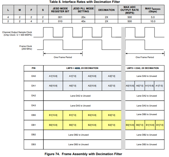
Can the Jesd204b link only be configured for 4222 and 2242 modes? Thanks.

Among the four outputs, can I choose any number of valid outputs?

Best Regards

Charlie Xiao

  • Hi Charlie,

    Correct, the only LMFS modes available for this device are LMFS=4222 and LMFS=2242. The internal JESD data stream is not configurable for different hardware pins. The figure which you have posted shows 8 lanes connected because this device is a spin of the ADS54J60 (which supports more than these 2 LMFS configurations) and the figure was not changed when making the ADS54J69 datasheet.

    Regards, Chase

  • Hi Chase,

    Thank you for your update. 

    I have another question:

    In 4222 mode: Which pins are the data allocated to? Is it 0 1 assigned to A channel and 0 1 of B channel? 

    Now the test is A channel lane0 and lane1 and B channel lane0 and lane1. The CGS and ILAS processes established by the Jesd204b link are basically normal, but the configuration information read in the second multi-frame of ILAS is not 4222. Not sure if it affects data transfer. Thanks.

    Regards, Charlie

  • You are correct. In 4222 mode, lanes 0 and 1 of both channels are the active lanes. See image below. Can you elaborate on what information is changed at the second multi-frame? Is it consistent?

    Regards, Chase

  • Hi Chase,

    This is the information of ILA.2:

    L=8, S=4, N=14

    F,M,K,CS,CF are all normal. Thanks.

    Regards, Charlie

  • Charlie,

    LID refers to lane ID which is different for each lane. The FCHK is the sum of the other parameters

    Regards, Chase

  • Hi Chase,

    From the configuration information read from ILA.2, the parameters L=8, S=4, N=14 sent by the ADC side do not match the actual configuration (L=4, S=2, N=16). Will it affect the transmission of data?

    Although the data can be transmitted now, I don't know if the precision of the data given by the ADC is 16bit. If you only look at the parameter N=14, its actual precision should be 14bit. Thanks.

    Regards, Charlie

  • Hi Chase,

    If you need more information, please remember to let me know. Thanks.

    Regards, Charlie

  • Charlie,

    These parameters should not affect any performance however I am checking with our design team on this. We suspect the parameters are like this as a result of this device being a spin of the ADS54J60, supporting the 8 lane mode... I will confirm with you after hearing back from our design team. There should be no padded 0's in the data since this is a 16-bit part. If the captured ADC data has two padded 0's at each second octet, then this would indicate a 14-bit resolution.

    Regards, Chase

  • Charlie,

    I've heard back from the design team regarding this topic. The parameters in the ILA table will be different and not match the actual configuration as this is a spin device.

    Regards, Chase