This thread has been locked.

If you have a related question, please click the "Ask a related question" button in the top right corner. The newly created question will be automatically linked to this question.

DAC38RF82EVM: configuration issues

Part Number: DAC38RF82EVM
Other Parts Discussed in Thread: TSW14J57EVM, , DAC38RF82

Hi team,

One of our customers has some questions to ask you. Requesting your kind guidance here.

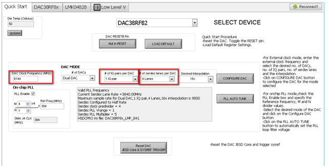
1. When configuring the DAC GUI, in the Quick Start tab, there are " 1 IQ pair " , " 2 IQ pair " , and " real input " in the" # of IQ pairs per DAC" , what do they mean?

2. what is meant  " # of serdes lanes per DAC "?

3 . what is the relationship between "DAC Clock Frequency (MHz) " and Sampling rate .

4. LED D8 " JESD sync " does not light on DAC38RF82EVM, how to resolve this, does it mean the DAC38RF82EVM and TSW14J57EVM are not synchronized successfully?

5. when clicking on “Reset DAC JESD Core & SYSREF trigger ”as per the procedure, LED D1 on the TSW14J57EVM goes off and on again, does it mean that the DAC EVM did not successfully establish a simultaneous connection to the TSW EVM?

Best Regards,

Amy Luo

  • Amy, please find my comments below

    1. The DAC38RF82 device can accept 1 IQ pair, 2 IQ pair, or just a real input. Depending on the selection, the input data format changes. These are found in Table 9 of the datasheet.

    2. This chooses the number of lanes to enable for the JESD interface. If using a single DAC, then this will reflect the total JESD lanes. If using dual DAC, then this number only reflects half of the total JESD lanes to be used.

    3. The DAC CLK frequency is the same as the sampling rate. This is different than the input data rate, which refers to the speed of the incoming digital data. The input data rate is equal to the DAC sample rate divided by the interpolation factor.

    4. This led should light when connected to the TSW and the link is established. For some reason, I think one of either the TSW14J56 or TSW14J57 this led will come up after the firmware is downloaded on the TSW board.

    5. Correct. When a link is established and data is being sent by the FPGA, led D3 on the TSW board will flash.

    Is there any particular mode the customer is needing help with? Is the customer able to establish a link and get an output while following the DACE38RF82EVM user guide?

    Regards, Chase

  • Hi Chase,

    I appreciated your support. But this customer sent me the following questions after that. I'm forwarding it below, could you please provide some troubleshooting suggestions

    1. Input 5V at DAC38RF82EVM J21 port, test the EVM TP21 (+5V IN) and TP22(GND) pins with a multimeter, test value approximately 4.05V,Is it not OK?

    2.  After I downloaded the firmware to the TSW14J57EVM, the D8 on the DAC38RF82EVM still does not light up, how can I resolve this?

    3. After clicking " Send " on the HSDC Pro, click "Reset DAC JESD Core & SYSREF TRIGGER" on the DAC38RF8xEVM GUI, D2 does not blink, D1 does not go out, how can I resolve this?

    4. After clicking "PLL AUTO TUNE ", in the "DAC38RF8x" tab, " PLL LF Voltage " will not automatically adjust to 3 or 4, does it mean that the PLL did not lock successfully? how can I resolve this?

    Best Regards,
    Amy Luo

  • Amy,

    The voltage should not read as 4V. This is not okay. Have the customer verify the supply is 5V while disconnected from the EVM and then ask them to re-verify the voltage while connected to the EVM. If the voltage gets pulled low to 4V again, the customer will have to return the board to the distributor which it was purchased and request a new EVM.

    Thanks, Chase